![]()
Engineering Pro Guides is your guide to passing the Mechanical & Electrical PE and FE Exams
Engineering Pro Guides provides mechanical and electrical PE and FE exam technical study guides, practice exams and much more. Contact Justin for more information.
Email: contact@engproguides.com
EXAM TOOLS
Thermal & Fluids - Hydraulic and Fluid Equipment
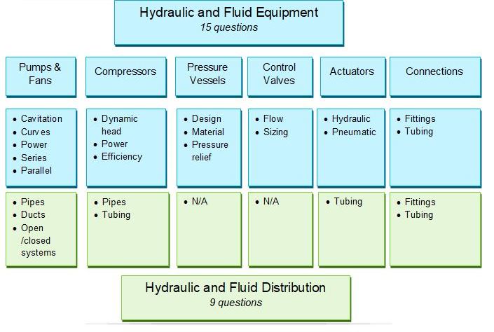
Principles - Hydraulic and Fluid Equipment - 15 of 80 Problems
“Hydraulic and Fluid Applications” accounts for approximately 24 questions on the Thermal & Fluids Mechanical PE exam. Hydraulic and Fluid Applications is broken up into two parts: (1) Hydraulic and Fluid Equipment and (2) Hydraulic and Fluid Distribution Systems. Hydraulic and Fluid Equipment is covered on this page.
Both topics, Equipment and Systems, point towards the topics of Hydraulics and Pneumatics. Hydraulics includes the equipment necessary to do work with liquid. This includes pumps, pipes, pressure vessels, control valves, actuators and connections, as shown in the simply hydraulic system.
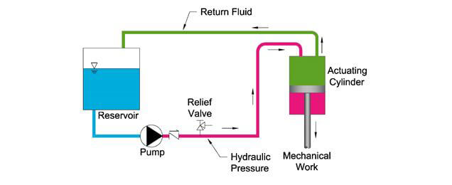
A simple hydraulic system consists of a reservoir that holds the hydraulic fluid, followed by a pump that pressurizes the fluid. The pressurized fluid in pink is then used to power an actuating cylinder to conduct mechanical work. In order to avoid over pressurization, there is a relief valve in the system. The green line shows the hydraulic fluid returning back to the reservoir when not needed.
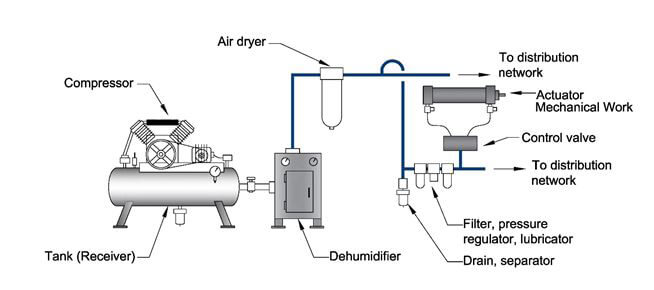
Pneumatics includes the equipment necessary to do work with air. This includes compressors, tubing, pressure vessels, control valves, actuators and connections, as shown in the simply pneumatic system.
The blue indicates the topics that are covered under Equipment and the green indicates the topics that are covered under Distribution Systems.
The information shown on this website is a sample of the material provided in the technical study guide and sample exam. See the STORE to purchase these items.
Pumps
Types of Pumps
There are three main types of pumps, centrifugal, rotary and reciprocating pumps. Rotary and reciprocating pumps are positive displacement pumps. This document will not cover positive displacement pumps in detail because they are not typically used in the Thermal & Fluids field. Centrifugal pumps are the most common type of pumps used in Thermal & Fluids. The following information is tailored to centrifugal pumps and should not be applied freely to positive displacement pumps.
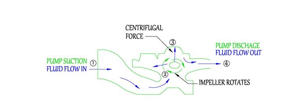
Centrifugal pumps operate on the principle of "centrifugal force", which is the conversion of rotational kinetic energy imparted by rotating impellers onto the liquid to produce a flow rate (kinetic energy) at a certain pressure (pressure energy). Fluid enters the pump at the center or eye of the impeller. The rotating impellers then push the fluid to the outer edges, imparting a flow rate and pressure. See the below figures for a diagram of the fluid flow.
There are two main families of centrifugal pumps (1) end suction pumps and (2) in-line pumps. These two families differ on the path the water takes from the inlet to the outlet. In end-suction pumps, the fluid enters the pump at the impeller and exits the pump at a 90 degree angle from the inlet. In-line pumps have parallel inlets and outlets.
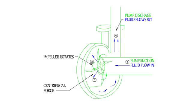
Centrifugal End Suction Pump - Cutaway: 90 Degree angle between suction and discharge - (1) Fluid flows into the center of the impeller, (2) as the impeller rotates,(3) the centrifugal force pushes fluid to the edges (4) until the fluid travels out the pump discharge.
Within each family are horizontal and vertical type pumps, which are characterized by the orientation of the pump shaft as either horizontal or vertical. In addition, pumps can be further classified by the number of stages that the fluid proceeds through. Finally the last classification is how the pump is connected to the motor. Pumps can be long-coupled where the pump is connected to the motor by a flexible coupling or they can be close-coupled where the connection between the pump and motor is through a rigid coupling.
Centrifugal In-Line Pump - Cutaway: In-line suction and discharge (1) Fluid flows into the center of the impeller, (2) as the impeller rotates,(3) the centrifugal force pushes the fluid to the edges (4)until the fluid travels out the pump discharge.
See technical study guide for more detail on Pumps, including (1) How to Determine Total Head, (2) How to Determine Net Positive Suction Head Available, (3) How to Read Pump Curves, (4) How to Use the Affinity Laws, and (5) How to Arrange Multiple Pumps in Series/Parallel. The Pumps topic is also followed by Fans.
Compressors
The compressor raises the temperature and pressure of a gas. The compressor is where the work takes place. The compressor is also the driving force that moves the gas through the cycles and pneumatic systems.
The compression of gas typically occurs isentropically for exam purposes, meaning that there is no change in entropy. Since the compressor is not completely efficient there will be an increase in enthalpy as the heat generated by the compressor is transferred to the gas.
Entropy - a measure of the amount of disorder in a thermodynamic system.
Enthalpy - a measure of the total energy in a thermodynamic system (sensible and latent energy).
The engineer should be knowledgeable of the 5 different types of compressors and their advantages and disadvantages, in order to determine when they should be used. The five types of compressors are centrifugal, scroll, reciprocating, screw and rotary. A brief overview of the different types of compressors is shown below.
- Rotary: The rotary type compressor compresses refrigerant gas through positive displacement. Positive displacement simply means that the pressure of the gas is increased by reducing the volume.
- Scroll: Similar to the rotary type compressor, the scroll compressor uses positive displacement to increase the pressure of the gas.
- Screw: The screw compressor consists of two interlocking screws. The gas moves through the screw from the beginning thread to the end thread, increasing the pressure as it moves to the discharge side.
- Reciprocating: A reciprocating compressor compresses gas through positive displacement. A piston type movement compresses gas as it enters the cylinder.
- Centrifugal: Centrifugal compressors are not like positive displacement compressors, these compressors rely on a rotating impeller to use its centrifugal force to move the gas to the outside diameter of the rotating impeller, which increases the velocity of the gas. The increased velocity is then translated into increased pressure.
See technical study guide for more detail on Compressors. The book includes information on Hermetic vs. Open Drive vs. Semi-Hermetic.
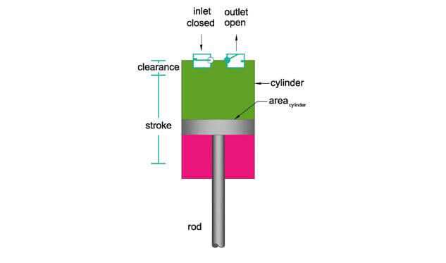
A single stage piston compressor has one stage of compression. It is comprised of a cylinder, which is the chamber of which the piston moves. The piston is the bottom of the plunger shape. The rod or stem is connected to the piston which moves the piston up and down.
The compression process begins as the piston draws air into the cylinder through the one-way intake valve. The cylinder fills up with air and then the piston compresses the volume of air as it decreases the volume. The distance at which the piston compresses the air is called the stroke. The stroke is not the entire length of the cylinder, because there is some clearance involved. Thus the total volume of the compressed air is the area of the cylinder multiplied by the stroke.
See technical study guide for more detail on Compressors. The book includes information on Two Stage Pistons, SCFM vs ACFM, Compressor Work and Compressor Efficiency.
Pressure Vessels
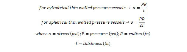
Pressure vessels are used to store both gases and liquids. Pressure vessels can come in a mixture of spherical and cylindrical shapes. The primary pressure vessels that you should know are the thin wall pressure vessels. These pressure vessels are used throughout the Thermal & Fluids field.
The thin walled pressure vessels make calculations easier. A thin walled pressure vessel is defined as having a ratio of radius to thickness as greater than 10

In a pressure vessel the pressure is assumed to be constant in all locations of the vessel.
See technical study guide for more detail on Pressure Vessels. The book includes information on Design Factors, Tensile and Yield Strength, Pressure Relief and Receivers.
Control Valves
Control valves are used to maintain a set pressure or flow to another piece of equipment. These valves are important because too little flow or pressure may cause one piece of equipment not to work and too much flow or pressure may be unsafe for the piece of equipment and personnel. These valves typically work automatically and are controlled by a control system and an actuator. The actuator is what provides the mechanical force to close and open the control valve. The control system is what tells the actuator when to operate and how to operate.
There are many types of control valves, like the globe valve, plug valve, angled valve, butterfly valve and 3-way valve. As an engineer you should understand each type of valve and when to use each type of valve. The different names of valves are given based on the shape of the valve. A good resource for valves is at any valve manufacturer’s websites, like Cla-Val, Apollo Valves and Powell Valves. However another good source is at the control valve webpage at Emerson Process’s website. If the link is not functional, please email me. You will find my contact information at the end of this book and the beginning of this book.
https://www.documentation.emersonprocess.com/groups/public/documents/book/cvh99.pdfThe various types of valves are good to understand but they are difficult to test on an exam, the sizing of the valves and the flow characteristics of a control valve is something that does fit this type of exam.
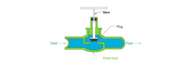
Globe Valve: A glove valve consists of a plug and a seat. The plug is raised and lowered to increase and decrease flow through the valve. A section view of a globe valve. As the valve is closed, the plug is lowered into the seat, which blocks the fluid flow from moving up and to the right of the valve.
See technical study guide for more valves like Ball and Butterfly Valves. Also included are flow characteristic graphs, valve sizing for liquids and air and critical point determination.
Actuators
Actuators are used to convert the energy in fluid (gas or liquid) into mechanical power. The power produced by the actuator and all the equations will be dependent on the flow rate of the fluid, the pressure and the efficiency of the actuator. A hydraulic actuator is an actuator that uses liquid as power and a pneumatic actuator is an actuator that uses gas as power.
The typical questions asked with actuators are to calculate the output force, the required pressure to output a force, the speed of the cylinder, the flow needed for a cylinder speed and the cylinder area required.
Cylinder Force
The force that a cylinder can produce is a result of the pressure of the fluid within the cylinder and the area that the cylinder acts upon.

In the equation above, the pressure describes the pressure of the hydraulic or pneumatic fluid. The area is the area that is conducting the mechanical power.
Fluid Pressure
If the force required and the cylinder area is given, then you can use the reverse of the previous equation to find the required pressure to achieve the mechanical work.

Cylinder Speed
If the force required and the cylinder area is given, then you can use the reverse of the previous equation to find the required pressure to achieve the mechanical work.
Fluid Flow
The next type of question is the opposite of the cylinder speed type question. If you are given the required cylinder speed and the area of the cylinder, then you must determine the required fluid flow. The below equation can be used for this type of problem.