- HOME
- FE EXAM
- PE EXAM
- DESIGN TOOLS
- COURSES
- STORE
- ABOUT
- CONSULTING
![]()
Engineering Pro Guides is your guide to passing the Mechanical & Electrical PE and FE Exams
Engineering Pro Guides provides mechanical and electrical PE and FE exam technical study guides, practice exams and much more. Contact Justin for more information.
Email: contact@engproguides.com
DESIGN
Condenser Water Pump Design Guide
Quickly determine pump sizing and complete pump schedule
Section 1.0: Introduction
The purpose of this guide is to provide the necessary background information on the Condenser Water Pump calculator to be able to use the calculator and to fill out a condenser water pump schedule. This guide covers the overall condenser water system, the calculator and the condenser water pump schedule. The overall condenser water system will help you to visualize how the condenser water pump fits within the overall system and will also help you to determine the hydraulically remote run for pressure drop calculations. Following the overall condenser water system, the inputs, outputs and references used in the calculator will be covered. The primary purpose of the calculator is to find the total dynamic head and net positive suction head available for use in the Condenser Water Pump Schedule. Lastly, each individual item within the Condenser Water Pump Schedule will be discussed in order to give you more knowledge on how to complete the schedule for your specific condenser water pump application.
The primary units that are used in the calculator are United States Customary System Units (USCS). As such, this guide focuses exclusively on the USCS. However, an SI version will also be provided in the future.
Section 2.0: Disclaimer
In no event will Engineering Pro Guides be liable for any incidental, indirect, consequential, punitive or special damages of any kind, or any other damages whatsoever, including, without limitation, those resulting from loss of profit, loss of contracts, loss of reputation, goodwill, data, information, income, anticipated savings or business relationships, whether or not Engineering Pro Guides has been advised of the possibility of such damage, arising out of or in connection with the use of this document/software or any referenced documents and/or websites.
This guide and calculator was created on the basis of helping engineers to increase their efficiency in completing calculations. However, the book and calculator was not intended to replace the engineering judgment necessary to interpret the results of any calculations. The engineer is still responsible for the calculations and results within the calculator.
Section 3.0: Overall Condenser Water System
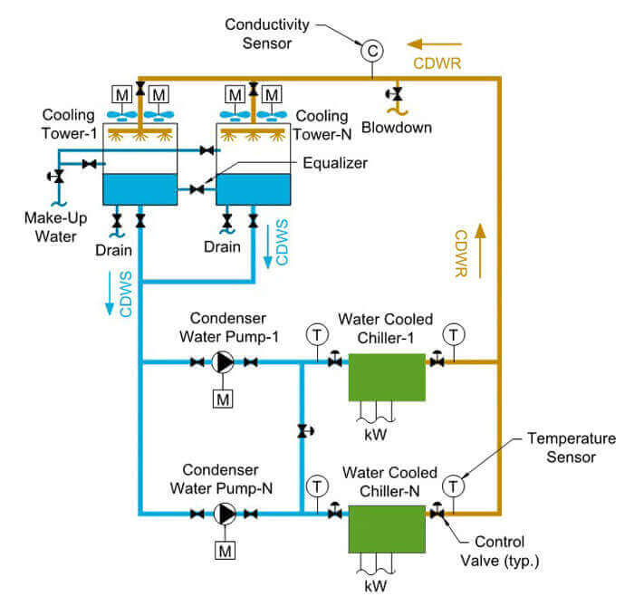
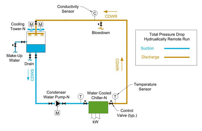
This guide covers the design and selection of a condenser water pump. The condenser water pump is a part of an overall condenser water system that often includes a chiller, piping, valves/fittings, water treatment, and a cooling tower. The condenser water pump is used to circulate condenser water either in an open or a closed circuit system. The condenser water pump circulates return condenser water from the chiller back to the cooling tower. The cooling tower then cools the condenser water, and the condenser water is supplied back to the chiller.
The condenser water pump must be sized properly to circulate the correct amount of flow at the correct pressure in order to achieve proper cooling within the building. If there is insufficient flow and pressure, then there will not be enough cooling and the building may get hot during periods of high cooling load. If there is too much pressure and flow, then the electrical system will be unnecessarily burdened and if there is no speed control, then electricity may be wasted due to excess pumping.
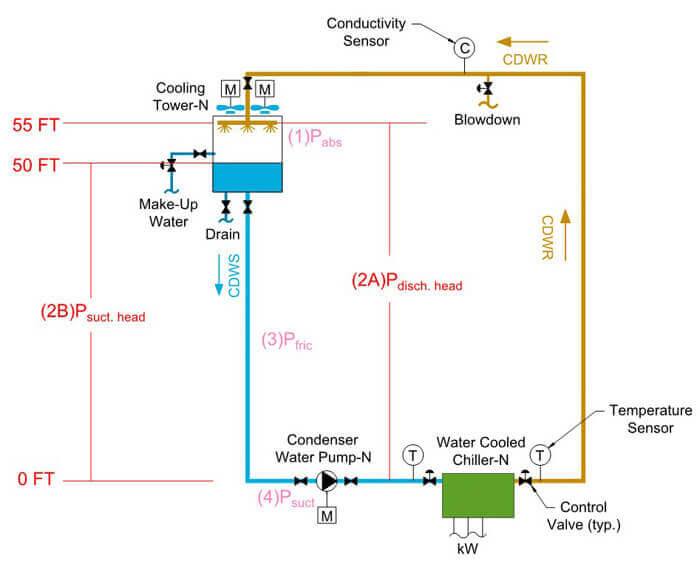
In an open circuit system the condenser water sprays into the fill of the cooling tower and comes into direct contact with the atmosphere, as shown below. In a closed circuit condenser water system, the condenser water is isolated by a coil in the cooling tower and never comes into direct contact with the atmosphere. An open circuit system is more commonly used in chiller plant design due to its lower first cost. A closed circuit cooling tower is used when maintaining the quality of the condenser water loop is desired, such as for a water source heat pump loop.
4.0 CONDENSER WATER PUMP CALCULATOR - INPUTS
In order to best use the condenser water pump calculator you should have an understanding of the inputs and how changes in the inputs will affect the output.
The chilled water pump must be sized properly to circulate the correct amount of flow at the correct pressure in order to achieve proper cooling within the building. If there is insufficient flow and pressure, then there will not be enough cooling and the building may get hot during periods of high cooling load. If there is too much pressure and flow, then the electrical system will be unnecessarily burdened and if there is no speed control, then electricity may be wasted due to excess pumping.
4.1 FLUID INFORMATION
The fluid information required includes the fluid type, temperature, density and kinematic/dynamic viscosity.

Fluid Type: There are several fluid types available for use in the calculator, including water, propylene glycol mixtures and ethylene glycol mixtures. If you select a fluid type from the drop down menu and a temperature, then the calculator will automatically fill in the properties for density, dynamic viscosity and kinematic viscosity. If your fluid type is not available in the drop down menu, then you must manually input all the values into the calculator, in order for the calculator to work. For condenser water, you will most likely be using “water” as your fluid type.
Temperature: The temperature is used by the calculator to automatically find the density, dynamic viscosity, kinematic viscosity and vapor pressure from the fluid properties built-in to the calculator. If you are not using one of the drop down fluid types, then the temperature is not necessary to get an output from the calculator. However, you will need to manually input the previously mentioned values to get an output from the calculator.
The typical condenser water temperatures are shown below as 5 and 15 degrees F higher than the 1% ambient design wet bulb temperatures. (For more information on cooling towers and condenser water temperatures, see the cooling tower white paper on https://www.engproguides.com/design.) You should select the average of the supply and return condenser water temperatures as the input temperature for the chilled water pump calculation.
- Supply Condenser Water: Design WB + 5 F
- Return Condenser Water: Design WB + 15 F
Density: The density is used in the calculations to find the Reynolds Number. The Reynolds Number is used to find the friction loss coefficient. The density is automatically found based on the fluid type and the temperature of the fluid.
Dynamic Viscosity: The dynamic viscosity is used in the calculator to find the Kinematic Viscosity. Dynamic viscosity is also known as absolute viscosity. Dynamic viscosity describes a fluid’s resistance to flow. The dynamic viscosity is automatically found based on the fluid type and the temperature of the fluid.
Kinematic Viscosity: The kinematic viscosity is used in the calculator to find the Reynolds Number. Kinematic viscosity is found by dividing the dynamic viscosity by the density.
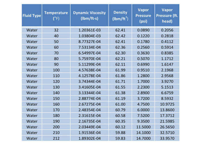
v (kinematic viscosity (ft^2)/s)=(μ (dynamic viscosity lbm/(ft-s)) )/(ρ (density lbm/(ft^3 )))Vapor Pressure: The vapor pressure is used to calculate the net positive suction head available. The vapor pressure is a function of the water temperature. As the temperature increases, the vapor pressure also increases. For example, the vapor pressure of water at 85 F is roughly 1.4 feet of head and the vapor pressure of water at 200 F is roughly 26.6 feet of head. The vapor pressure is the minimum pressure required to keep water in its liquid form. For example, if the pressure of water at 200 F is changed to 20 feet of head, then the water will vaporize. The vapor pressure is automatically found based on the fluid type and fluid temperature.
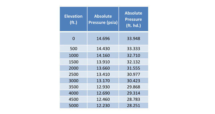
Absolute Pressure: The absolute pressure is used to calculate the net positive suction head available. The absolute pressure is the pressure acting upon the fluid at the cooling tower. This is also known as atmospheric pressure. Absolute pressure varies as a function of elevation. At sea level, the absolute pressure is 14.7 PSIA or 34 feet of head.
4.2 Pipe Information
The calculator requires you to insert the pipe section information which includes the flow rate, pipe material, pipe type, pipe size and length of pipe. A different pipe section should be used if any of these variables are changed.

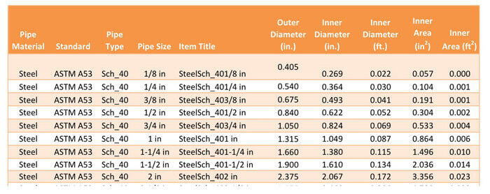
There are various pipes available for use in the calculator but you can also add your own pipe information. The pipes built-in to the calculator include, ASTM A53 Steel (Schedule 40 & 80), ASTM B88 Copper (Type K, L & M), ASTM D2241 PVC (SDR 26) and ASTM F2389 Polypropylene (DR 9). These are the most common pipes used in condenser water pipe application. If you have a special case, then please use the references sheet to add in your pipe information or contact Justin via email contact@engproguides.com.
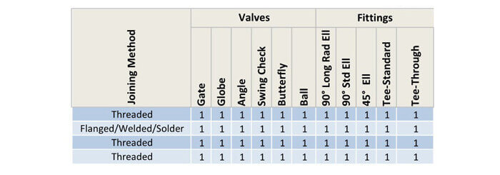
4.3 Valve & Fitting Information
The valves and fittings section requires you to put in the values for each fitting that are on a certain pipe section. A pipe section is defined as having the same flow rate and same pipe information.
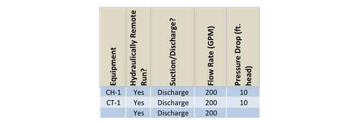
4.4 Equipment Information
The equipment section requires you to insert the flow rate and pressure drop for each piece of equipment. You should also indicate if the equipment is on the hydraulically remote run. Remember, only items listed as hydraulically remote will be used to calculate the pressure drop for the condenser water pump.
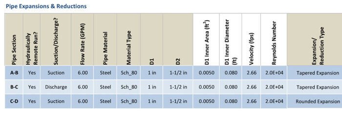
4.5 Pipe Expansions & Reductions Information
Pipe expansions and reductions use different equations to calculate pressure drops than those used for pressure loss through straight length of piping and through valves & fittings. Pipe expansion and reductions are dependent on the ratio between the two different pipe diameters. For example, the pressure drop through a 4”- 6” pipe expansion is less than the pressure drop through a 2” – 6” pipe expansion.
4.6 Elevation Difference
The elevation difference is used to determine the net positive suction head available. This requires you to input the pump discharge elevation head and pump suction elevation head.
Pump Suction Elevation Head: This is the difference in elevation between the pump suction and the cooling tower basin. The zero elevation point is taken as the pump suction. If the cooling tower basin is above the pump suction, then the elevation head will be positive.
Pump Discharge Elevation Head: This is the difference in elevation between the pump discharge and the piping discharge at the top of the cooling tower. The zero elevation point is taken as the pump discharge. If the condenser water piping discharge at the top of the cooling tower is above the pump discharge, then the elevation head will be positive.
5.0 CONDENSER WATER PUMP CALCULATOR - OUTPUTS
This section covers the equations that use the inputs and references to create the outputs in the calculator.
5.1 Fluid Velocity
The first equation uses the inputs from the pipe information section and the user input flow rate to find the fluid velocity in the pipe. When you choose the pipe material, pipe type and pipe size, the calculator will automatically determine the inner area from the table within the references. If the combination of pipe material, pipe type and pipe size are not in the calculator then a “N/A” will appear in the velocity column. You should double check to make sure the combination exists before proceeding.

5.2 Reynolds Number
The first equation uses the inputs from the pipe information section and the user input flow rate to find the fluid velocity in the pipe. When you choose the pipe material, pipe type and pipe size, the calculator automatically calculates the reynolds number.
The next equation calculates the Reynolds Number. This equation uses the velocity from the previous equation along with the pipe inner diameter and the fluid properties (density & viscosity).

The Reynolds Number classifies the fluid flow into either (1) Laminar, (2) Transition or (3) Turbulent. The breakdown between these three classifications is defined below. The friction calculations are most accurate with fluid flow in the turbulent region. For this reason, the calculator will highlight in red any Reynolds Number that is below the turbulent region.

5.3 Friction Factor
The friction factor is found through the Colebrook Equation. The Colebrook Equation relates the friction factor to the Reynolds Number and the relative roughness.

Iterative Process: Since the friction coefficient is on both sides of the equation, you must use an iterative process to find the friction coefficient. You must first choose a value for the friction coefficient on the right side of the equation and then solve for the friction coefficient on the left side. Then use the friction coefficient that you just computed and plug-in this value to the right side of the equation and repeat the process. The process ends when the right and left side friction coefficients converge to nearly the same number. The calculator completes this process by running nine iterations.
Turbulent Flow: This equation only works for turbulent flow. A different equation is used for laminar flow. Luckily in practical condenser water applications, flow is nearly always turbulent. However, the calculator does incorporate conditional formatting to visually tell you if the flow is not turbulent. You should use your knowledge of the turbulent range from the previous section to ensure that your flow calculations are in the turbulent range.
5.4 Pressure Drop
The next step in the calculator is to calculate the pressure drop for the four different categories, (1) Piping, (2) Valves & Fittings, (3) Equipment and (4) Expansions/Reducers. Each of the four categories has their own specific equations, but (1) and (2) are included in the same line item on the calculator The next paragraphs will go through the calculations for each of the four categories.
5.4.1 Pressure Drop – Piping & Valves/Fittings
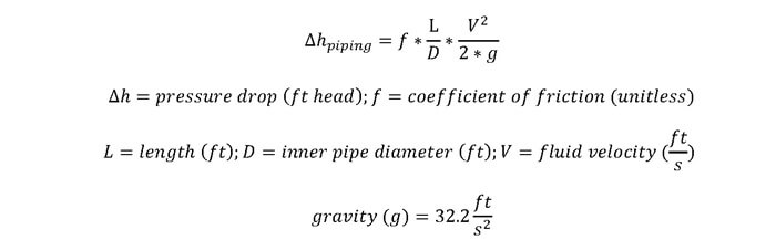
The pressure drop for a straight length of piping is found through the friction factor and the Darcy Weisbach equation. This equation uses the velocity, friction factor, pipe inner diameter and the length of piping to calculate the pressure drop. For more details, see the equation below. The output for this equation is the pressure drop in units of feet head.
The pressure drop through valves and fittings is found through the 3-K method. The 3-K method uses three K-values to characterize each type of valve and fitting. These three K-values are K1, Kinf and Kd. These K-values are used with the Reynolds Number and nominal pipe diameter to find the final K-value.

Since, the calculated K-value is a function of Reynolds Number and nominal pipe diameter, the K-value is applicable for various pipe sizes, pipe materials, fluids and fluid velocities. Once you have the K-value, the K-value is used to calculate the pressure drop through the valves and fittings.

5.4.2 Pressure Drop – Equipment
There are no equations governing the pressure drop in equipment section. In this section of the calculator you can input the values for pressure drop at equipment. Typical equipment includes chillers, strainers, fan coils, flow meters, control valves and air handling unit coils. The pressure drop through this equipment at a specified flow rate must be provided by the manufacturer of the equipment. Typically, the manufacturer will provide a single value that indicates the pressure drop at a specified flow rate (GPM). This is typical of chillers, fan coils and air handling units. Other times, a manufacturer will provide a graph that shows the pressure drop at various flow rates. This is typical of flow meters, control valves and strainers.
5.4.3 Pressure Drop – Expansions/Reducers
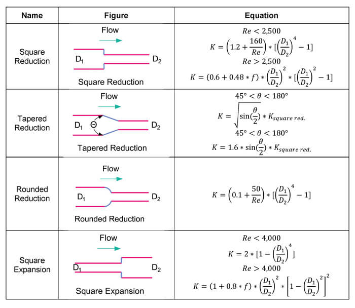
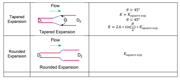
The last pressure drop calculation is the pressure drop due to pipe expansion and reductions. These pipe expansions and reductions occur when there is a change in pipe size. This calculation is dependent on the shape of the pipe size change. For example, the shape could be square, rounded, tapered and the pipe size change could be sharp or gradual. Each type of pipe size change has its own equation
An example of the equations used in the calculator include the square reduction equation. First, you must solve for the K-value.


The calculator automatically ensures that you are meeting the requirements of the equation. There are other equations for each pipe expansion/reduction and each set of requirements as shown in the table below.
Once, the K-value is calculated, then the calculator calculates the pressure drop with the below equation.

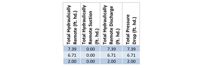
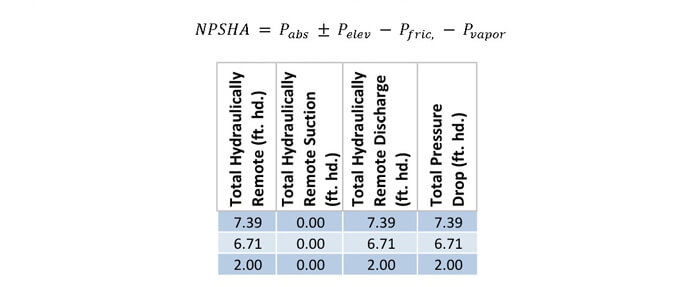
5.4.4 Total Hydraulically Remote Pressure Drop – Suction & Discharge
Two of the last columns on the right side of all the pressure drop categories is the total pressure drop on the hydraulically remote run of the suction or discharge piping. If you select “Yes” under hydraulically remote run and “Suction” or “Discharge”, then this column will show the pressure drop in the section of pipe, pipe reducer/expansion section or equipment under “Suction Hydraulically Remote Run” or “Discharge Hydraulically Remote Run”. This value is used to calculate the total net positive suction head available and also the total dynamic head of the condenser water pump.
5.5 Net Positive Suction Head Available
The calculator also calculates the net positive suction head available, which is used to choose a pump that can operate at the design conditions without reaching cavitation. Cavitation occurs when the suction pressure (head) at the pump is less than the vapor pressure of the water. If the suction pressure is lower than the vapor pressure, then small vapor bubbles form. When these bubbles reach the pump, the pressure of the fluid increases and the bubbles implode causing damage to the impellers and other parts of the pump. This is what is known as cavitation.
Suction head is defined as the pressure at the inlet of the pump and net positive suction head is the difference between the suction head at the inlet and the vapor pressure of the fluid at the inlet of the pump.

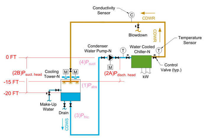
Suction head is found by determining all the pressures acting upon the fluid whether positive or negative in the suction piping. The following figure best describes all the pressures that can be acting upon a pump.
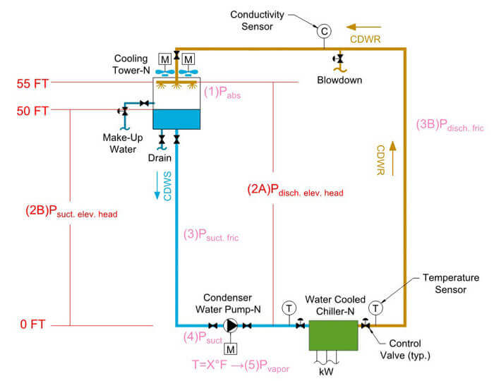
(1) Pabs: This pressure refers to the absolute pressure acting on the fluid. If the tank is pressurized, then the value is pre-determined. If the tank is open to the atmosphere, then the pressure is equal to 1 atmosphere [atm] or 14.7 psia or 33.9 ft. of water.
(2) Pelev: This pressure identifies the elevation difference between the top surface of the liquid and the pump centerline on the suction side of the piping. This value can be positive or negative and is measured in “feet of head”. In order to calculate this value, you only need to find the Pelev for the suction piping.

(3) Psuct. fric: The suction friction pressure or head is the amount of pressure lost due to friction in the piping, fittings, equipment, valves, etc. leading from the fluid source to the pump.
(4) Psuction: Finally, all of the pressures leading to the pump are summed and the resulting value is the suction pressure at the pump due to both the water and absolute pressure.

(5) Pvapor: The vapor pressure of the water is found by simply looking up fluid property tables and finding the vapor pressure at the operating temperature. Water is the most common fluid used in condenser water pumping systems and a table of corresponding vapor pressure and temperatures are shown below. Use the ASHRAE Fundamentals book to find similar tables.
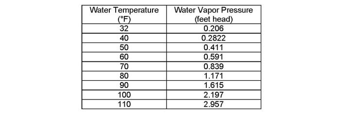
From the table above, it can be seen that as the temperature of the water increases, the pressure at which vaporization will occur also increases. The issue of cavitation becomes even more critical at higher temperatures.
Finally, the equation for NPSHA, found at the beginning of this section can be summarized as:
The net positive suction head required (NPSHR) is an important criteria when selecting the condenser water pump.
NPSHR is provided by the pump manufacturer and it is the minimum required pressure at the suction of the pump. The NPSHA must be higher than the NPSHR to prevent cavitation.

The calculator also shows the net positive suction head available at the top of the calculator as a final sum of all friction loss values, suction elevation head, vapor pressure and absolute pressure.
5.6 Total Dynamic Head
The total dynamic head sums up all the friction losses in both the discharge and suction piping for all three categories (piping/fitting/valves, equipment/misc. & reducers/expansions). Total dynamic head also includes the discharge elevation head minus the suction elevation head. The final equation is shown below.

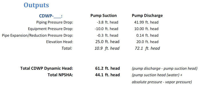
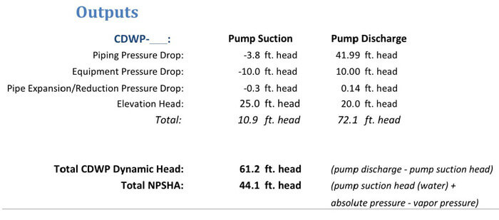
If you use the example below, you can see an example as to how the above equation is used.
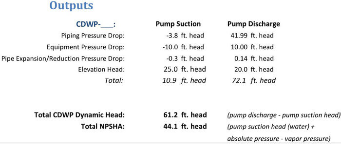
The following equation shows total dynamic head solved with the previous equation.

The following equation shows total dynamic head solved by taking the difference between the pump discharge pressure and the pump suction pressure.

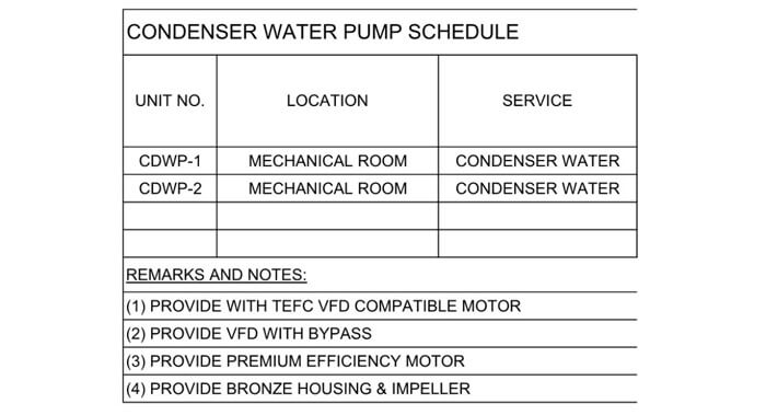
6.0 Condenser Water Pump Schedule
The design and selection of a condenser water pump typically results in the completion of the condenser water pump schedule. A sample schedule is provided in the calculator as a separate sheet. The condenser water pump schedule provides all the necessary design requirements to purchase the condenser water pump. This includes, pump type, flow rate, total dynamic head, pump speed, efficiency, net positive suction head available and motor information. There are a few other non-pump design requirements like the location and unit number and a section called remarks for pump design requirements that do not fit under the previously mentioned categories.
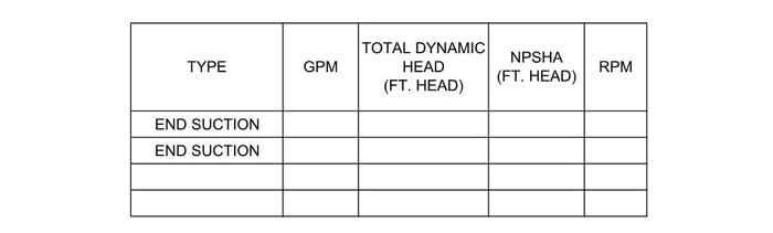
6.1 Flow Rate (GPM)
The flow rate for the condenser water pump is typically determined by the maximum condenser water flow of the chiller(s).
6.2 Total Dynamic Head (Feet Head)
The total dynamic head is found through the excel calculator. This total dynamic head is the total pressure drop in the most hydraulically remote run from the condenser water pump supply from the pump to the condenser water return of the pump.
6.3 Net Positive Suction Head Available
The net positive suction head available will be an output of the calculator. The net positive suction head available is equal to the suction head pressure at the pump less the vapor pressure of the fluid at the pump suction. The condenser water pump must have a net positive suction head required that is less than the net positive suction head available.
6.4 Service
This column is used to clarify the fluid of the pump, since these schedules may often be used as a general pump schedule. A general pump schedule could include condenser water pumps, condenser water pumps, hot water pumps, etc. In this case, the service column could be removed since the entire schedule is dedicated to condenser water pumps.
6.5 Location
Condenser water pumps are typically located in a mechanical room with or near the water cooled chiller(s). The condenser water pump should be located with sufficient net positive suction head to ensure proper operation of the pump.
6.6 Pump Types
There are three main types of pumps, centrifugal, rotary and reciprocating pumps. Rotary and reciprocating pumps are positive displacement pumps. This guide will not cover positive displacement and reciprocating pumps in detail because they are not typically used for condenser water pumps.
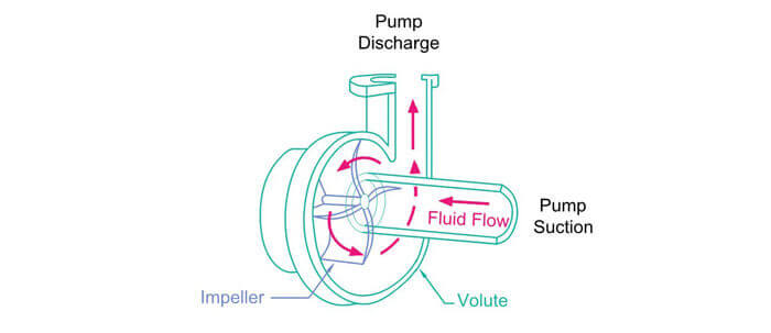
Centrifugal pumps are the most common type of pumps used for condenser water applications. The following information is tailored to centrifugal pumps and should not be applied freely to positive displacement pumps.
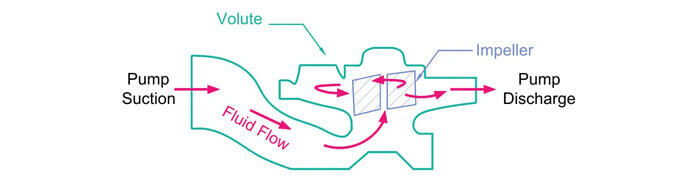
Centrifugal pumps operate on the principle of "centrifugal force", which is the conversion of rotational kinetic energy imparted by rotating impellers onto the liquid to produce a flow rate (kinetic energy) at a certain pressure (pressure energy). Fluid enters the pump at the center or eye of the impeller. The rotating impellers then push the fluid to the outer edges, imparting a flow rate and pressure. There are two main types of centrifugal pumps, in-line and end-suction. These two types are discussed below.
Within each centrifugal pump type (end suction & in-line) are horizontal and vertical type pumps, which are characterized by the orientation of the pump shaft as either horizontal or vertical. In addition, pumps can be further classified by the number of stages that the fluid proceeds through. Finally the last classification is how the pump is connected to the motor. Pumps can be long-coupled where the pump is connected to the motor by a flexible coupling or they can be close-coupled where the connection between the pump and motor is through a rigid coupling. The table below is a summary of the most common condenser water pump types.
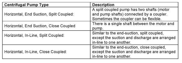
The same four types of pumps also can be found with a vertical arrangement.
Another type of pump that is used for larger flow rates is the split case type. This centrifugal pump type has two chambers (split case) as opposed to the single chamber for end suction and in-line pumps.
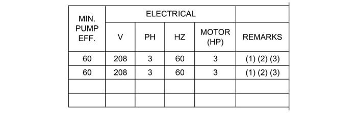
6.7 Pump Efficiency
The typical pump efficiencies are within the range of 60% to 80%. You should select a pump that has its best efficiency point near your design operating point (typically around 10%). For example, if the best efficiency point of a pump is 72%, then you should choose this pump if your operating point is greater than 62% efficiency.
6.8 Pump Speed
The pump speeds available for condenser water pumps include 1,200, 1,800 and 3,600 RPM. When you choose the pump speed, you must first ensure that the pump manufacturer has that speed available. Lower pump speeds are preferred because the increased number of rotations will cause increased wear and tear. Bearings lifetimes are rated based on number of rotations, so if the rotations are reduced, then the bearings should have a longer life. This is true of all rotating objects. The most common pump speed is 1,760 RPM and then 3,500 RPM. The 1,160 RPM is sometimes used for smaller pumps with motors less than 5 HP.
Sometimes the pump manufacturer will indicate a speed slightly below 1,200, 1,800 or 3,600. This is because the motor is an induction motor as opposed to a synchronous motor. This means that electrically the rotation will be 1,200, 1,800 or 3,600 RPM, but the shaft will lag slightly behind this rotation.
6.9 Motor
The motor provides the necessary mechanical power to rotate the impeller within the pump. A motor takes in electrical power and converts the power to rotation. The motor must be able to meet the brake horsepower requirements of the pump. This is based on the pump flow rate, pump pressure and the efficiency of the pump.
With these inputs, the brake horsepower of the condenser water pump is calculated with the following equation.

The pump needs a motor to provide the power to spin the pump. The motor will need to provide more than the pump power because there will be losses due to motor inefficiencies. Typically motor efficiencies range from 90% – 95%.

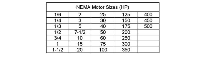
The calculated motor horsepower must be less than the available motor horsepower ratings. The available horsepower motor ratings are shown in the table below.
Pump manufacturers have online software that automatically shows the available pumps for a given flow rate and pressure drop. The software will show the speed (RPM), efficiency, brake-horsepower (BHP) and horsepower (HP) for the various pump types that can meet the required flow rate and pressure drop.
Sample Online Pump Selector: https://www.pacopumps.com/PumpSelect.aspx
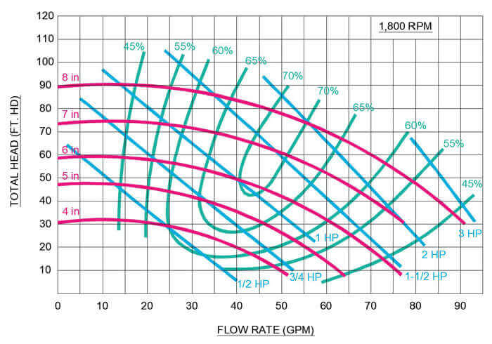
Although the pump selection tool makes it very easy to select pumps, you should also know how to select pumps via the pump curves. A pump curve shows the pressure and flow rate operating points for a pump operating at various speeds or impeller diameters. If a pump speed is selected (1,200, 1,800 or 3,600) for a pump, then the pump curve graph will show multiple pump curves at various impeller diameters. If an impeller diameter is selected, then the pump curve graph will show multiple pump curves at various speeds. The following figure shows a specific pump speed, with multiple pump curves at various impeller diameters.
The graph also shows curves of pump horsepower in blue. These curves are created by calculating the horsepower based on the pressure, flow rate and pump/motor efficiency at a point. The efficiency curves shown on the figure are found based on a series of tests of the actual pump.
6.10 Remarks, Additional Features
A condenser water pump will often require additional features besides the basic requirements that were discussed previously. A brief discussion of the most common
Non-Overloading Pump: A non-overloading pump is a pump with a sufficiently sized motor that can provide enough power at all operating points along a pump curve. For example, in the previous figure a non-overloading pump with 6” impeller diameter will have a 1-1/2 HP motor. At every point on the red curve, the horsepower required is less than the 1-1/2 blue HP curve.
Premium Efficiency Motor: A premium efficiency motor describes a motor that has a minimum efficiency specific to each motor horsepower in compliance with NEMA Premium Efficiency Motor Standards. The motor standards can be found in the below links. As an example, an energy efficient 5 HP/1,800 RPM motor will have an efficiency of 87.5% and a premium efficient motor will have an efficiency of 89.5%.
- https://www.nema.org/Policy/Energy/Efficiency/Pages/NEMA-Premium-Motors.aspx
- https://www.energy.gov/sites/prod/files/2014/04/f15/amo_motors_handbook_web.pdf
Variable Frequency Drive: A variable frequency drive is used to increase the speed of the pump rotation, which causes the pump curve to shift up and down. This causes the pump to provide more flow/pressure as the speed is increased and less flow/pressure as the speed is decreased.