![]()
Engineering Pro Guides is your guide to passing the Mechanical & Electrical PE and FE Exams
Engineering Pro Guides provides mechanical and electrical PE and FE exam technical study guides, practice exams and much more. Contact Justin for more information.
Email: contact@engproguides.com
EXAM TOOLS
Equipment & Components - 18 of 80 Problems
This section accounts for approximately 18 questions on the HVAC & Refrigeration Mechanical PE exam This section focuses on the energy and mass balance equations that govern various HVAC and Refrigeration processes. These processes include evaporation, condensation and mixing. The important concept to understand is that in each process, energy and mass of the fluid is conserved, even if the fluid is changing from gas to liquid or liquid to gas.
The NCEES outline indicates the following equipment and components will be on the PE Exam: 1. Cooling towers and fluid coolers, 2. Boilers and furnaces (e.g., efficiencies, fuel types, combustion), 3. Heat exchangers (e.g., shell and tube, plate and frame), 4. Condensers/evaporators (e.g., chillers, variable refrigerant flow, heat pumps), 5. Pumps/compressors/fans (e.g., laws, efficiency, selection), 6. Cooling/heating coils, 7. Control systems components (e.g., valves, dampers), 8. Refrigerants (e.g., properties, types) and 9. Refrigeration components (e.g., expansion valves, accumulators).
The equipment discussed in this section includes the most common pieces of equipment and systems that are on the PE exam. The next section uses the equipment and components and puts them together into various systems.
1. Air handling and distribution equipment: fans, dampers, cooling/heating coils and heat exchangers.
2. Fluid handling and distribution equipment: pumps, cooling towers, fluid coolers, heat exchangers and valves.
3. Refrigerant handling and distribution equipment: chillers, condensers, evaporators and compressors.
4. Heating handling and distribution equipment: boilers and furnaces.
Cooling Towers
Cooling towers are mechanical pieces of equipment that function on the principle of evaporative cooling. Evaporative cooling is the process by which a liquid is cooled to a lower temperature by evaporating a small portion of the liquid into an airstream. Relatively dry air moves through a falling liquid and as the air moves it picks up water vapor from the liquid, thereby increasing the air’s moisture content. In order for the liquid to evaporate, the liquid needs a heat source to meet the latent heat of vaporization. This heat source is the sensible heat loss from the remaining liquid.
A cooling tower consists of two fluid flows, the air flow and the water flow. The water flow starts from the top of the cooling tower. Warm water is pumped to a series of nozzles. The nozzles’ purpose is to break up the water into tiny droplets to increase the surface area of the water that is in contact with the air stream. The droplets then fall through a fill material, which also serves to break up the droplets further to increase the surface area of the water. As the water moves downward it steadily decreases in temperature as heat is lost due to evaporation. Finally the water collects at the basin and is sucked out distributed to its required location.
The air flow starts at the bottom of the tower, where cold dry air is brought into the cooling tower where it comes into contact with the water droplets. As the air moves upward through the tower it picks up water vapor and slightly increases in temperature. Prior to exiting the cooling tower, the air must travel through the drift eliminators which is a series of baffles. The purpose of the drift eliminators is to catch any suspended water droplets in the air stream and return them to the fill.

CHARACTERIZING COOLING TOWERS
The following section provides information on the different types of cooling towers used in the HVAC and Refrigeration field. This information is merely provided to give the engineer additional background on cooling towers.
Mechanical vs. Natural Draft Cooling Towers:
There are two main categories of cooling towers: (1) Mechanical draft and (2) Natural draft cooling towers. Natural draft cooling towers move air based on the difference in buoyancy of the airstream inside and outside of the cooling tower. Mechanical draft cooling towers move air through the cooling tower by means of a mechanical fan. In the HVAC and Refrigeration field, mechanical draft cooling towers are the primary type of cooling tower.
Induced vs. Forced Draft Cooling Towers:
Induced and forced draft cooling towers are both mechanical draft type fans and differ by the location of their fan. Forced draft fans blow air into the cooling tower and are located at the airstream entrance into the cooling tower. Induced draft cooling towers on the other hand, have the fans located at the exit of the airstream for the cooling tower and suck air into the cooling tower.
Counter-flow vs. Cross-flow Cooling Towers:
Counter-flow and cross-flow cooling towers are characterized by the relationship between the air flow and water flow. In a counter flow tower the air and water flow are at 90 degrees to each other. The water is falling downwards and the air is moving across from either left to right or right to left. In a cross-flow tower, the air and water flows have directly opposing directions. The water is falling downwards and the air is moving upwards.

The following figure is a schematic of a forced mechanical draft, counter flow cooling tower. The fans are located at the air inlets, near the bottom of the cooling tower. Also the air flow counters the water as the water drops downward through the fill material.

The following figure is a schematic of a forced mechanical draft, cross flow cooling tower. Since this cooling tower is forced draft, the fans are again located at the inlet of the cooling tower near the bottom. The air flows counter or perpendicular to the water as the water falls downward through the fill.

The following figure is a schematic of an induced mechanical draft, counter flow cooling tower. The fan is located at the exit of the cooling tower and air is sucked or induced through the cooling tower. This cooling tower is also a counter flow type, where air flows upward through the fill and counters the downward moving water droplets.

The following figure is a schematic of an induced mechanical draft, cross flow cooling tower. Again the fan is located at the exit of the cooling tower. This cooling tower is a cross flow cooling tower, where air flows perpendicular through the fill as it crosses the falling water droplets.

Cooling Tower Performance
The professional engineer must be able to properly design and size and select a cooling tower to fit the HVAC and Refrigeration application. Cooling towers are characterized by two terms the approach and the range. The range of the cooling tower is the difference between the entering and exiting temperatures of the cooling tower water.
Range=T_(water,in)-T_(water,out)
The approach or approach to wet bulb is the temperature difference between the water out and the wet bulb temperature of the air.
Approach=T_(water,out)-T_(air in,WB)
The approach is important because it describes the level of performance of the cooling tower. The smaller the approach the better the cooling tower is at providing cooling. The wet bulb temperature of the entering air is the lowest the temperature of the exiting water can reach. If a cooling tower has a 0 degree approach then the cooling tower is using all of the available heat exchange from the air to cool the water. Typical approaches are in the range of ~10 °F.
Approach also leads to another important term in determining the performance of cooling towers, called effectiveness. Effectiveness is a term used to describe how effective the cooling tower is at cooling the water or how close the actual temperature difference between the water temperatures in and out is to the maximum temperature difference. The maximum temperature difference that a cooling tower can produce is the difference between the water temperature in and the air wet bulb temperature.
Effectiveness=Range/(Range+ Approach)
The range is important because when used in conjunction with the water flow rate, the capacity of the cooling tower can be found. The capacity and the amount of cooling provided by the cooling tower are found by multiplying the flow rate of the cooling water by the difference in temperature at the inlet and outlet of the cooling tower, using the following equation, Q = mc∆T and for a simplified equation to use during the test, follow the derivation below.

Cooling Tower Water Loss and Make-up
In a cooling tower, water is lost due to multiple sources such as evaporation, drift and blow-down. The first term, evaporation, is calculated through the following equation, where the assumption is made that the total heat loss is due to the heat loss through evaporation.

The second water loss is due to drift. Drift is the amount of water that is carried out through the airstream. Drift eliminators provided prior to the discharge are best described as a maze of baffles that the air must travel through before exiting to atmosphere. The drift eliminator trap the water droplets that get picked up by the exiting air and send the droplets back to the fill material. Typical water loss due to drift is less than 0.2%.
The third major source of water loss is due to blow-down. Blow-down is required because as water is evaporated it leaves behind the total dissolved solids (TDS), which increases the concentration of the TDS in the water. In order to bring the concentration of the TDS back to normal conditions so that it may be used safely with the equipment, the high concentrated TDS water is drained regularly and this is what is referred to as blow-down. The water is then replaced with fresh water and this is referred to as make-up water.
Boilers & Furnaces
Furnaces
Furnaces are mechanical pieces of equipment used for space heating. Furnaces consist of a burner with a combustion air intake, fuel intake and an igniter. The hot combustion flames are routed through a heat exchanger, where heat is exchanged to the cold air as it is blown across the heat exchanger coils. Warm air is then blown to the space and the combustion gases/products exit the furnace through an exhaust vent pipe.
The fuel that is most commonly used is natural gas. Furnaces can be used in both residential and commercial situations.
TYPES OF FURNACES
The two main types of furnaces are condensing and non-condensing furnaces. The traditional non-condensing furnace operates in the initial description of a furnace. These furnaces can have efficiencies in the range of 80% to 84% AFUE. A condensing furnace takes the combustion products that were initially routed to the exhaust vent and passes them through another heat exchanger. This extracts more heat to the air and cools the combustion products to a temperature where water begins to condense out of the air. Because of the water, this second heat exchanger is made of a corrosive resistive material. A condensing furnace can have efficiencies in the range of 90% to 98% AFUE.
EFFICIENCY
The annual fuel utilization efficiency (AFUE) is the term used by manufacturers to rate the annual efficiency of their furnaces. It describes the ratio of the amount of useful heat out of the furnace compared to the amount of fuel input to the furnace. This efficiency rating is regulated by the Department of Energy (DOE) and is used to take into account the constant on/off operation and seasonal effects on the furnace. The DOE requires that all furnaces have efficiencies greater than 78% AFUE.
Steady state efficiencies are also provided by the manufacturer and indicate the best efficiency of the furnace when operated at peak conditions.
Boilers
See technical study guide for discussion on boilers.
Heat Exchangers
Heat exchangers are mechanical devices designed to exchange or transfer heat from a hot fluid to a cold fluid. Heat exchangers are used heavily throughout the HVAC and Refrigeration field, for example a condenser or evaporator in a chiller is simply a heat exchanger. A cooling or heating coil is a heat exchanger that transfers heat from one fluid to another fluid. A chilled water air handling unit transfers heat from the hot air to the chilled water.
There are many different types of heat exchangers that will be briefly discussed, but first it is important to understand the two classifications of heat exchangers, counter-flow and parallel flow heat exchangers. These two classifications describe the relation of the direction of flow between the cold and hot fluid. First the parallel flow heat exchanger, this heat exchanger has both the cold and hot fluids entering at the same end of the heat exchanger. At the beginning of the heat exchanger there is a large difference between the cold and hot fluids and at the end of the heat exchange the difference between cold and hot is reduced, refer to the figure below.

The counter-flow heat exchanger is opposite of the parallel flow heat exchanger. The cold and hot fluids enter at opposite ends. The figure below shows the counter-flow heat exchanger, notice the change in directional arrows.

LOG MEAN TEMPERATURE DIFFERENCE (LMTD)
In heat exchangers that do not have a phase change, heat is transferred from the hot fluid to the cold fluid through the temperature difference between the cold and hot. However, in a heat exchanger as shown in the previous figures, the temperature difference between the cold and hot fluids is not always constant and depends on the location in the heat exchanger. Thus the log mean temperature difference is used. The LMTD describes the logarithmic average temperature difference between the cold and hot fluid through a generic heat exchanger (counter or parallel). LMTD cannot be used for heat exchangers with a phase change like a boiler or condenser. The equation for LMTD is shown below.

The LMTD is then used to calculate the total heat exchanged by the heat exchanger through the following equation. The U-value is the heat transfer coefficient of the heat exchanger which is given by the heat exchanger manufacturer. The Area value is the total area where heat exchange occurs, which is given by the heat exchanger manufacturer.

HEAT BALANCE
Often times in the HVAC and Refrigeration field, a heat balance is conducted on a heat exchanger to show that a balance of heat loss from the hot fluid is shown as a heat gain to the cold fluid. For example, cooling coils are heat exchangers that transfer heat from air to water. The heat balance governing this heat transfer would be as shown below.

If there is a phase change, then the following equation can be used. Heat balances are discussed further in the Refrigeration Section, Mechanical Systems and the Psychrometrics section. Basically, heat balances are integral to the HVAC and Refrigeration field, but luckily the equations governing a heat balance are fairly simple.

Heat Transfer Key Equations


Condensers & Evaporators
Refer to thermodynamics section for a background of condensers and evaporators and its role in the vapor-compression cycle.
There are three main equipment types that operate based on the vapor-compression cycle: chillers, variable refrigerant flow (VRF) systems, and heat pumps.
Chillers
The entire vapor compression cycle is contained within the chiller. The chiller essentially transfers heat from the evaporator to the condenser through the use of a refrigerant and the refrigeration cycle.
The evaporator within the chiller is used to cool water. This water, known as chilled water, is then distributed to air handlers throughout the building. Chilled water is typically supplied to the distribution system at 44oF and returned at 58oF for a 14oF differential temperature. (45oF chilled water supply and 55oF return is also commonly seen.)
Heat is rejected from the compressor within the chiller to a heat sink. There are two main mediums that are used to reject the heat from the compressor: air and water, which gives way to the two main chilled water system types: Air Cooled Chiller and Water Cooled Chiller. The air cooled system contains fans within the chiller. The fans are used to blow ambient air over the condenser. The water cooled system uses a cooling tower and evaporative cooling principles to transfer the heat from the condenser using water, known in the system as condenser water. Refer to the beginning of this section for a discussion on cooling towers.
Air cooled chillers have lower capital investment costs because the system is contained within one equipment. They also do not require additional costs to supply and treat the water at the cooling tower. However, as cooling plants get larger, water cooled systems tend to have greater overall energy savings. As a general rule of thumb, air cooled systems are typically selected for cooling load requirements under 300 tons and water cooled systems are selected for loads over 300 tons.
VRF
A variable refrigerant flow (VRF) system is a direct expansion (DX) system, meaning the refrigerant is used to directly cool the air, unlike a chiller which uses chilled water as the medium. In the VRF system, the equipment is split between the Condensing Unit and the Fan Coil Unit. The condensing unit contains the compressor, condenser, and expansion valve, while the fan coil unit contains the evaporator and a fan. Refrigerant is distributed between the condensing unit and fan coil unit (FCU). The refrigerant is supplied to the FCU as liquid and returns as gas. The air flow at the fan remains constant, while the refrigerant flow varies to maintain the temperature in the space.
Like the chiller, the condenser within the VRF system can be cooled with either an air cooled or a water cooled system.
VRF systems are generally more efficient than chilled water systems, but are higher in initial cost. The distribution of refrigerant requires much less space than ductwork to distribute air, but the VRF system requires much more fan coils and thus overall inventory of equipment. Due to the lacking economy of scale, VRF systems are favored in buildings with cooling loads below 150 tons.
Heat Pump
A heat pump uses the same vapor compression cycle, except its objective is to heat instead of cool. The heat pump uses the condenser to heat a space (or water) and the evaporator grabs heat from the exterior. Using the refrigeration cycle, the heat pump is able to produce heat at 3 to 4 times the efficiency of an electric heating coil, i.e. the COP is around 3 and 4. The heat source is either from the ambient air, known as an air source heat pump, from water, known as water source heat pump, or from the ground, known as ground source heat pump. Ground source heat pumps are less common due to its high costs. Air source heat pumps are much more common, but are less reliable in the winter as the heat sink becomes cooler. Heat pumps are also commonly integrated within the VRF system, allowing the units to switch between heating and cooling.
Pumps
The main focus of the pump section is to help the engineer develop an understanding of the major skills and concepts needed for the PE exam. These concepts include (1) determining total head, (2) determining net positive suction head, (3) reading pump curves, (4) using affinity laws. However, in order to focus on these skills and concepts, the engineer will require a brief introduction on pumps, types of pumps and how they work.
There are three main types of pumps, centrifugal, rotary and reciprocating pumps. Rotary and reciprocating pumps are positive displacement pumps. This document will not cover positive displacement pumps in detail because they are not typically used in the HVAC and Refrigeration field. Centrifugal pumps are the most common type of pumps used in HVAC and Refrigeration. The following information is tailored to centrifugal pumps and should not be applied freely to positive displacement pumps.
Centrifugal pumps operate on the principle of "centrifugal force", which is the conversion of rotational kinetic energy imparted by rotating impellers onto the fluid to produce a flow rate (kinetic energy) at a certain pressure (pressure energy). Fluid enters the pump at the center or eye of the impeller, there the rotating impellers push the fluid to the outer edges, imparting a flow rate and pressure. See Figures 1 and 2 for a diagram of the fluid flow.
There are various types of centrifugal pumps, but there are two main families of centrifugal pumps are (1) end suction pumps [refer to Figure 1] and (2) in-line pumps [refer to Figure 2]. These two families differ on the path the water takes from the inlet to the outlet. In the end-suction pumps, the fluid enters the pump at the impeller and exits the pump at a 90 degree angle from the inlet. The in-line pumps have parallel inlets and outlets.
Within each family are horizontal versus vertical pumps, which are characterized by the orientation of the pump shaft as either horizontal or vertical. In addition, pumps can be further classified by the number of stages that the fluid proceeds through. Finally the last classification is how the pump is connected to the motor. Pumps can be long-coupled where the pump is connected to the motor by a flexible coupling or they can be close-coupled where the connection between the pump and motor is through a rigid coupling.

Pump Curve
Pump curves are created by the manufacturers of the pumps through a series of tests and describe the operating points for a specific impeller diameter and pump type. The curve plots the corresponding flow rates at varying pressures

Pump Affinity Laws
It is often necessary to determine how a pump will operate under differing operating conditions. The operating conditions of a pump that can most readily be changed are the impeller diameter and the rotational speed of the pump. In order to predict how the pump will behave prior to changing the speed or the impeller diameter.
The first affinity law is that the flow rate (Q) is directly proportional to the size of the diameter of the pump impeller (D) and/or the rotational speed (N) of the pump.

The second affinity law is that the total head (H) is directly proportional to the square of the size of the diameter of the pump impeller (D) and/or the square of the rotational speed (N) of the pump.

The third affinity law is that the power (P) is directly proportional to the cube of the size of the diameter of the pump impeller (D) and/or the cube of the rotational speed (N) of the pump.

Fans
Fan Terms
Fans are provided in HVAC and Refrigeration systems to distribute conditioned air, to provide ventilation or to exhaust un-wanted air.
Mechanical Horsepower (MHP): Mechanical horsepower is the measure of the power produced by the fan, a function of the air flow rate measured in cubic feet per minute (CFM) and the total static pressure (TSP) measured in “in. wg.”.
MHP=(CFM*TSP[in.wg])/6,356
Brake Horsepower (BHP): Brake horsepower is the measure of the power drawn by the motor to turn the fan, a function of the fan efficiency and the mechanical horsepower.
BHP=MHP*(1/(fan efficiency))
Horsepower (HP): Horsepower is the motor size. It is a function of the BHP and the motor efficiency.
HP=BHP*(1/(motor efficiency))
*upsize HP to nearest motor size
Velocity Pressure (VP): Velocity pressure is defined as the pressure caused solely by moving air.
VP=FPM/4005 [in.wg]
Static Pressure (SP): Static pressure is the pressure caused solely by compression, the outward force on a duct.
Total Pressure (TSP): Total static pressure is the sum of the velocity pressure and the static pressure at any point.
Fan Types
- AXIAL
- PROPELLER
- TUBE-AXIAL
- CENTRIFUGAL
Fan Curves
The fan curve is graph depicting the various points that the fan can operate. It indicates the amount of CFM the fan will provide at a given total static pressure, which is dependent on the connected ducted system. Fans should be selected to operate at the stable region. The stable region is the area on the fan curve where there is a single flow rate [CFM] value for ever pressure value. In the unstable region, a pressure value can have multiple CFM values, which will cause the fan system to surge. The stable region also has very little change in CFM for large changes in total pressure.

The second curve that works in conjunction with the fan curve is the system resistance curve. This curve is summation of all the friction losses in the ducting system at varying CFM's. Typically, the friction losses are summed up at the design CFM values, then this design point is connected to the 0,0 point by an upward sloping square polynomial curve, as shown below. If for example, the ducting system has a closed damper or dirty filter, this will cause the curve to shift to the left. If a damper is opened or the dirty filter is cleaned then the curve will shift to the right.

Combining the system curve with the selected fan curve, determines the operating point of the fan system, indicated in the figure below in green. Following the vertical line down determines the CFM and the horizontal line from that point indicates the operating total pressure. During system operation as dampers close, the system curve shifts toward the right in red. This movement decreases the amount of CFM delivered by the fan. The opposite occurs as dampers open in the system, the amount of CFM delivered by the fan increases.

It has been shown that the amount of CFM blown by a fan can be changed by shifting the system resistance curve. However, the volumetric flow rate can also be changed by changing the speed of the fan, which shifts the fan curve.

Fan Affinity Laws
Often times a fan’s speed or impeller diameter will be changed. If the fan is a centrifugal fan, then the change in performance of the fan can be predicted quickly through the affinity laws.
First if the impeller diameter is held constant and the speed of the fan is changed, then flow rate varies directly with the speed, available pressure varies with the square of the speed and the power use varies with the cube of the speed.

Second if the speed is held constant and the impeller diameter of the fan is changed, then flow rate varies directly with the diameter, available pressure varies with the diameter of the speed and the power use varies with the cube of the diameter.

Multiple Fans
FANS IN PARALLEL
A parallel arrangement of fans is characterized by the same pressure increase across each fan and the total flow is the sum of flows through each individual fan. In the figure below, the total flow is shown as x1 + x2 + x3, where xn is the flow through fan “n”. The resulting total pressure is equal to each individual fan pressure, since they are all the same

FANS IN SERIES
Fans in series are characterized by the same flow across each fan and the total pressure increase is the sum of the pressure increase through each individual fan. In the figure on the following page, the total flow is shown simply as y, which is consistent throughout each fan. The resulting total pressure is equal to sum of each fan’s individual pressure increase, y1 + y2 + y3, where yn is the resulting fan pressure increase at fan “n”.

Compressors
Refer to the Thermodynamic section for compressor principles.
The compressor raises the temperature and pressure of a gas. The compressor is where the work takes place. The compressor is also the driving force that moves the gas through the cycles and pneumatic systems.
The compression of gas typically occurs isentropically for exam purposes, meaning that there is no change in entropy. Since the compressor is not completely efficient there will be an increase in enthalpy as the heat generated by the compressor is transferred to the gas.
Entropy - a measure of the amount of disorder in a thermodynamic system.
Enthalpy - a measure of the total energy in a thermodynamic system (sensible and latent energy).
The engineer should be knowledgeable of the 5 different types of compressors and their advantages and disadvantages, in order to determine when they should be used. The five types of compressors are centrifugal, scroll, reciprocating, screw and rotary. A brief overview of the different types of compressors is shown below.
- Rotary: The rotary type compressor compresses refrigerant gas through positive displacement. Positive displacement simply means that the pressure of the gas is increased by reducing the volume.
- Scroll: Similar to the rotary type compressor, the scroll compressor uses positive displacement to increase the pressure of the gas.
- Screw: The screw compressor consists of two interlocking screws. The gas moves through the screw from the beginning thread to the end thread, increasing the pressure as it moves to the discharge side.
- Reciprocating: A reciprocating compressor compresses gas through positive displacement. A piston type movement compresses gas as it enters the cylinder.
- Centrifugal: Centrifugal compressors are not like positive displacement compressors, these compressors rely on a rotating impeller to use its centrifugal force to move the gas to the outside diameter of the rotating impeller, which increases the velocity of the gas. The increased velocity is then translated into increased pressure.
See technical study guide for more detail on Compressors. The book includes information on Hermetic vs. Open Drive vs. Semi-Hermetic.
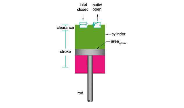
A single stage piston compressor has one stage of compression. It is comprised of a cylinder, which is the chamber of which the piston moves. The piston is the bottom of the plunger shape. The rod or stem is connected to the piston which moves the piston up and down.
The compression process begins as the piston draws air into the cylinder through the one-way intake valve. The cylinder fills up with air and then the piston compresses the volume of air as it decreases the volume. The distance at which the piston compresses the air is called the stroke. The stroke is not the entire length of the cylinder, because there is some clearance involved. Thus the total volume of the compressed air is the area of the cylinder multiplied by the stroke.
See technical study guide for more detail on Compressors. The book includes information on Two Stage Pistons, SCFM vs ACFM, Compressor Work and Compressor Efficiency.
Cooling/Heating Coils
In the HVAC and Refrigeration field, cooling and heating coils are used to exchange heat to/from air to a heat exchange fluid. A heat exchange fluid is flown through the coil and as air is passed over the coil, the air is either heated or cooled. Coils consist of a metal box framing, which holds a series of copper tubes in staggered rows and columns.

The amount of heat that is transferred is related to the amount of surface area that the air is in contact with. In order to increase surface area, the size of the tubes may be decreased and more tubes can be provided, the number of rows increased or the amount of fins per inch are increased. Aluminum or copper fins are provided on each tube to increase the amount of surface area. Coils are rated by the height of the fins and the number of fins per inch.
Cooling and Heating Coil Fluids
There are several different types of heat exchange fluids used in cooling/heating coils.
Refrigerant: Hot refrigerant gas or cool refrigerant liquid can be used in a coil to provide either heating or cooling. In a heating-coil, cool air is passed over a coil containing hot gas. Heat is exchanged to the cool air, which warms the air. The heat lost by the refrigerant gas causes it to condense to a liquid. In a cooling-coil, warm air is passed over a coil containing cool refrigerant liquid. Heat is exchanged to the cool refrigerant liquid, causing it to evaporate. The warm air loses heat, thereby decreasing the air temperature.
Water: Chilled water or hot water can be used in a coil to provide either heating or cooling. The air temperature is either raised or lowered as heat is transferred to raise or lower the temperature of the chilled or hot water.
Steam: Steam can be provided to a coil to provide heating. Steam enters the coil and as the air passes over the coil its air temperature increases. As the steam loses heat, it condenses to its liquid form.
Cooling and Heating Coil Terms
It is important to be able to understand the following terms, (1a) Apparatus Dew Point or (1b) Effective Surface Temperature and the (2) Contact Factor
Apparatus Dew Point or Effective Surface Temperature is the temperature at which all air would be cooled to if the cooling coil was 100% effective. The ADP must be located on the saturation curve, refer to the psychrometric chart below. The ADP, leaving coil conditions and the entering coil conditions are located on the same line.

How close the leaving coil condition is to the apparatus dew point is a function of the contact factor. The bypass factor describes the percentage of air that is not cooled to the ADP. The air that is bypassed remains unchanged from the entering coil conditions. The bypass factor is a function of the airflow, number of rows, surface temperature, number of fins per inch, height of fins and many other construction attributes of coils. The origin of the bypass factor is not important, but the use of the bypass factor in calculations is important. The bypass factor can be found through the use of (a) enthalpy, (b) dry bulb temperature or (c) humidity ratio. The contact factoris the inverse of the bypass factor. It describes the amount of air that is contact with the coil and that is cooled to the ADP.

(De)Humidification Systems
In the HVAC and Refrigeration field, humidification and dehumidification systems are used to transfer moisture to/from the air. These types of systems are sized based on the amount of moisture, measured in pounds of water per hour that is added or removed to the air.

Humidifiers
Humidifiers are used to add moisture to air typically in order to achieve the best conditions for human occupancy. In dry areas, low humidity causes moisture to evaporate from people’s skin, creating the feeling that it is much colder than the dry bulb temperature indicates. Other times humidifiers are used to maintain best humidity levels for equipment or produce.
There are two main types of humidifiers, (1) Steam and (2) Evaporative humidifiers.
(1) Steam Humidifiers, also known as isothermal humidifiers, add moisture to air without the change in dry bulb temperature, hence isothermal humidifier. Steam is created through an external means like a gas fired boiler or electric boiler. Then the steam is typically directly injected into the air stream. It is common to assume that the temperature of the air will rise since steam is 212 F. However, it is important to think of steam as water vapor and as it is added to air, it will correspond to an upward movement on the psychrometric chart [Pt 1 to Pt 2].

(2) Evaporative Humidifiers, also known as adiabatic humidifiers, add moisture to air without a change in enthalpy, hence adiabatic humidifier. Evaporative humidifiers do not require an external energy source like Steam Humidifiers. Evaporative humidifiers work by blowing dry air over water or through water droplets. The energy to vaporize the water comes from the dry air. As the air releases heat to vaporize the water, the air also cools. On the psychrometric chart, adiabatic humidification is shown as an upward-left movement, along a constant enthalpy line. It is constant enthalpy because the enthalpy lost to sensible cooling is gained by latent heating [humidification].
Evaporative humidifiers operate on the same principle as air washers, evaporative coolers and cooling towers. These principles will be discussed in the Cooling Tower section. D
De-Humidifiers
De-Humidifiers are used to remove moisture to air typically in order to achieve the best conditions for human occupancy. In humid areas, high humidity causes the feeling that it is much hotter than the dry bulb temperature indicates. Other times de-humidifiers are used to maintain best humidity levels for equipment or produce. De-humidifiers are especially important in preventing mold and mildew from forming.
There are two main types of de-humidifiers, (1) Condensing and (2) Desiccant de-humidifiers.
(1) Condensing de-humidifiers or cooling humidifiers work by decreasing the temperature of the incoming air so that it is unable to hold moisture, which causes condensation. A cooling coil acts a dehumidifier. In the Psychrometric chart below, hot, humid air enters the coil and leaves as cool air. The amount of water vapor removed from the air is shown in red. In some cases the air is reheated in order to lower the relative humidity and increase the dry bulb temperature.

(2) Desiccant de-humidifiers or chemical dehumidifiers use desiccants to adsorb water from air. As the air loses its water vapor, the heat from condensing the water vapor is gained by the air stream, which causes the air to increase its dry bulb temperature. A desiccant de-humidifier is shown as a downward-right movement, along the constant enthalpy line (adiabatic).
Control System Components
Control Valves
Control valves are used to maintain a set pressure or flow to another piece of equipment. These valves are important because too little flow or pressure may cause one piece of equipment not to work and too much flow or pressure may be unsafe for the piece of equipment and personnel. These valves typically work automatically and are controlled by a control system and an actuator. The actuator is what provides the mechanical force to close and open the control valve. The control system is what tells the actuator when to operate and how to operate.
There are many types of control valves, like the globe valve, plug valve, angled valve, butterfly valve and 3-way valve. As an engineer you should understand each type of valve and when to use each type of valve. The different names of valves are given based on the shape of the valve. A good resource for valves is at any valve manufacturer’s websites, like Cla-Val, Apollo Valves and Powell Valves. However another good source is at the control valve webpage at Emerson Process’s website.
The various types of valves are good to understand but they are difficult to test on an exam, the sizing of the valves and the flow characteristics of a control valve is something that does fit this type of exam.
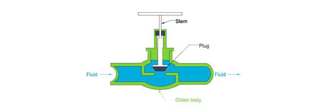
Globe Valve: A glove valve consists of a plug and a seat. The plug is raised and lowered to increase and decrease flow through the valve. A section view of a globe valve. As the valve is closed, the plug is lowered into the seat, which blocks the fluid flow from moving up and to the right of the valve.
See technical study guide for more valves like Ball and Butterfly Valves. Also included are flow characteristic graphs, valve sizing for liquids and air and critical point determination. On the air side the technical study guide discusses dampers. For both dampers and valves, you also need an actuator to operate the valve or damper. These are also discussed in the technical study guide.
Actuators
Actuators are used to convert the energy in fluid (gas or liquid) into mechanical power. The power produced by the actuator and all the equations will be dependent on the flow rate of the fluid, the pressure and the efficiency of the actuator. A hydraulic actuator is an actuator that uses liquid as power and a pneumatic actuator is an actuator that uses gas as power.
The typical questions asked with actuators are to calculate the output force, the required pressure to output a force, the speed of the cylinder, the flow needed for a cylinder speed and the cylinder area required.
Cylinder Force
The force that a cylinder can produce is a result of the pressure of the fluid within the cylinder and the area that the cylinder acts upon.

In the equation above, the pressure describes the pressure of the hydraulic or pneumatic fluid. The area is the area that is conducting the mechanical power.
Fluid Pressure
If the force required and the cylinder area is given, then you can use the reverse of the previous equation to find the required pressure to achieve the mechanical work.

Cylinder Speed
If the force required and the cylinder area is given, then you can use the reverse of the previous equation to find the required pressure to achieve the mechanical work.
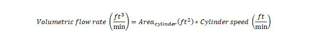
Fluid Flow
The next type of question is the opposite of the cylinder speed type question. If you are given the required cylinder speed and the area of the cylinder, then you must determine the required fluid flow. The below equation can be used for this type of problem.
Refrigerants
Refrigerants are fluids used in the commercial HVAC field to transfer heat from one source to another. For example, in a water cooled chiller, refrigerant is used to remove heat from chilled water and transfer heat to condenser water. Or in a typical residential split air conditioner system, refrigerant is used to remove heat from the indoor air and transfer that heat to the outdoors through the use of a condenser.
The main requirement for a fluid to be classified as a refrigerant is the ability to transfer heat. Refrigerants must also be safe in order to be used for commercial and residential air conditioning purposes. Refrigerants are classified by the following information: (1) Flammability, (2) Toxicity, (3) Global Warming Potential (GWP), (4) Ozone Depleting Potential (ODP) and (5) Operating Pressure. The flammability and toxicity classifications are shown in ASHRAE 15. Be familiar with ASHRAE 15
Refrigerants can be split into four different types, (1) Hydrocarbons, (2) Chlorofluorocarbons, (3) Hydroclurofluorocarbons and (4) Hydrofluorocarbons.
- Hydrocarbons consist of hydrogen and carbon. Some examples of hydrocarbons include methane, ethane, propane and butane. Hydrocarbons like propane and isobutene can be used in vapor compression cycles for refrigeration, but most commonly hydrocarbons are used in the combustion process.
- CFCs consist of carbon, with the chemical addition of chlorine and fluorine. Common CFCs include R-12 and R-11, which were used heavily in air conditioning, vapor compression cycles. Unlike hydrocarbons, CFCs are non-flammable. However, CFCs when improperly handled and released into the atmosphere have been found to deplete the ozone layer. For this reason, CFCs have been scheduled to be phased out and in the United States. In fact, CFCs are no longer used in new air conditioning machines.
- HCFCs consist of hydrogen and carbon, with the chemical addition of chlorine and fluorine. The most common HCFC is R-22, which was used heavily in air conditioning. HCFCs are non-flammable. They are also no longer used in new air conditioning machines in the United States, because they contain the ozone harmful element, chlorine. The Montreal Protocol requires that HCFC's be decreased in consumption and production, until HCFC's are completely phased out in 2030. Two specific HCFC’s, 22 and 142B, have been phased out of new equipment in 2010, with the complete phase out of these refrigerants in 2020 (existing and new equipment).
- HFCs have been substituted for CFCs because they have an ozone depletion potential of zero and contain no chlorine. HFCs are also being substituted for HCFCs because they are currently the most efficient refrigerants that do not harm the ozone, since they do not contain chlorine. However, HFCs are also planned to be substituted in the future because of the greenhouse gases that are emitted.

Ozone Depleting Potential
Ozone Depleting Potential [ODP]: The ODP is an index developed to identify how damaging a substance is to the ozone. The reference point from which all substances are compared is CFC-11. CFC-11 is assumed to have an ODP of 1, more damaging chemicals have a higher ODP and less damaging chemicals have a lower ODP. A summary of chemicals and their ODP is shown in the table below. Refrigerants with chlorine have a higher ODP. It is estimated that each chlorine atom destroys 100,000 ozone molecules.

Global Warming Potential
Global Warming Potential [GWP]: The GWP is an index developed to identify the potential for a substance to prevent infrared radiation from leaving the earth's atmosphere. The reference point, from which all substances are compared, is carbon dioxide. CO2 is assumed to have a GWP of 1, chemicals with a higher potential to contribute to global warming have a higher GWP and those with a lower potential have a lower GWP. A summary of chemicals and their GWP is shown in the table below.

Boiling Points
Low pressure refrigerants boil at a lower temperature, high pressure refrigerants condense at a higher temperature.
One key principle that must be understood for Refrigeration is the relationship between the boiling/condensing point of a fluid, in this case a refrigerant, and the temperature and pressure of the refrigerant. A refrigerant liquid’s boiling point is a function of the vapor pressure of the refrigerant vapor that is in equilibrium with the refrigerant liquid. If the pressure is low, then there is a smaller force acting upon the refrigerant liquid, thus it will take a lower temperature to boil the refrigerant liquid. For example, water at a pressure of 1 atmosphere or 14.696 PSI will boil at 212 F. However, if the water was at a pressure of 0.122 PSI, then the water will boil at 40 F.

When a low pressure refrigerant changes from its liquid phase to a gas phase, it can absorb much more heat than if it were to simply increase in temperature. The same is also true when a high pressure refrigerant changes phase from its gas phase to a liquid phase, it release much more heat than if it were to decrease in temperature. The energy required to change the phase of a liquid from a liquid to a gas is called the latent heat of evaporation. The energy released to change the phase of a gas to a liquid is called the latent heat of condensation.
Refrigerant Components
Step 1 - Evaporator
The vapor compression cycle is the primary cycle used in commercial refrigeration systems.
The vapor compression cycle starts at (Step 1) the evaporator, with cold, low-pressure, liquid refrigerant. It absorbs heat and evaporates to a low-pressure gas. Then the gas is (Step 2) Compressed to a high-pressure, high-temperature gas and (Step 3) condensed to a high pressure gas. Finally, the gas is condensed at the (Step 4) expansion device to a cold, low-pressure liquid refrigerant.

Step 1: Evaporator. The first step in the vapor compression cycle is the evaporator, which can also be called a liquid cooler. The evaporator is simply a heat exchanger. Heat is exchanged from the warm medium (air or water) to the cold, liquid refrigerant. The heat gained by the liquid refrigerant causes it to change phases to a refrigerant gas. The refrigerant liquid gains the heat necessary to overcome the latent heat of evaporation, in order to change to a gas. There are two types of evaporators, (1) an air cooled evaporator and (2) a water cooled evaporator. Figure below shows the (1) air cooled evaporator which is most commonly referred to as a direct expansion system. In this evaporator, warm air from an air conditioned space is cooled and redistributed to the space. Also shown in the figure below is the water cooled system, where chilled water return is cooled and supplied to the chilled water distribution system.

The most common system is the direct expansion system. This system is prevalent throughout smaller systems, like those serving residential systems. In this system, the hot air from the space is used to directly evaporate the refrigerant to a hot gas. Note that the hot air from the space is roughly ~75 °F and the refrigerant liquid is typically 40 °F. The 75 °F room air is cooled down to ~55 °F and then distributed back to the space. In a water-cooled system, which is more common for larger commercial systems, chilled water typically at 55 °F is cooled by the evaporator down to ~45 °F. The colder chilled water is then supplied to another heat exchanger, where air is cooled and then distributed to the space.
Besides the two different types of evaporator systems, there are also different types of heat exchangers used in refrigeration. The most common heat exchangers include: (1) Shell and Tube, (2) Tube in Tube and (3) Brazed Plate.
(1) Shell and Tube: This heat exchanger is the most common and consists of copper pipes arranged in a coil that is constructed in a cylindrical shell. One fluid is provided in the shell and contacts the outer surface of the inner tubes. Another fluid is contained inside of the tubes. Heat exchange occurs in the shell at the outer surface of the tubes. Often times aluminum fins are provided on the copper pipes. These fins provide more surface area for heat exchange to occur.
(2) Tube in Tube: A tube is constructed in a tube, sealed separately to keep the fluids in one tube from contaminating the other. Heat exchange is conducted at the outer surface of the inner tube and the inner surface of the outer tube.
(3) Brazed Plate: This type of heat exchanger consists of multiple thin plates separated by a small distance. Each plate either carries the hot or cold fluid. Heat exchange occurs between the surface areas of each plate.
As previously mentioned the evaporator acts as a heat exchanger with a cold side and a hot side. The cold side consists of a mixture of refrigerant gas and liquid. At this point, the partial liquid-gas refrigerant mixture moves through the evaporator, picking up heat from the hot side. But instead of heating the gas, the heat is used to boil the remaining liquid. It is important for the evaporator to boil all of the liquid, prior to the refrigerant entering the compressor in the following step. Once all the liquid has boiled, the liquid-gas mixture turns into a refrigerant gas (vapor), called a saturated vapor. Any additional heat will now increase the temperature of the refrigerant vapor, into a region called super heat. Any release in heat will cause some of the gas to condense back to a liquid.
It is important for the engineer to understand that the amount of cooling provided through the evaporation of the refrigerant liquid is much more than simply increasing the temperature of the refrigerant liquid. For example, R-134a takes 92.82 Btu of heat to change 1 lb of refrigerant from liquid to gas. While it takes 0.204 Btu of heat to increase 1 lb of refrigerant gas by 1°F.
Step 2 - Compressor
The vapor compression cycle is the primary cycle used in commercial refrigeration systems.
The vapor compression cycle starts at (Step 1) the evaporator, with cold, low-pressure, liquid refrigerant. It absorbs heat and evaporates to a low-pressure gas. Then the gas is (Step 2) Compressed to a high-pressure, high-temperature gas and (Step 3) condensed to a high pressure gas. Finally, the gas is condensed at the (Step 4) expansion device to a cold, low-pressure liquid refrigerant.
Step 2: Compressor: The next step is where the refrigerant gas is compressed by the compressor, which raises the temperature and pressure of the gas. The compressor is where the work takes place. The compressor is also the driving force that moves the refrigerant through the vapor compression cycle and prepares the refrigerant before it enters the condenser. It is important that the refrigerant gas is raised to a temperature that is above the temperature of the fluid in the condenser. This will allow heat to be transferred from the refrigerant to the condenser fluid. The compression of the refrigerant gas occurs isentropically, meaning that there is no change in entropy. Since the compressor is not completely efficient there will be an increase in enthalpy as the heat generated by the compressor is transferred to the refrigerant gas.
Entropy - a measure of the amount of disorder in a thermodynamic system.
Enthalpy - a measure of the total energy in a thermodynamic system (sensible and latent energy).
The engineer should be knowledgeable of the 5 different types of compressors and their advantages and disadvantages, in order to determine when they should be used. The five types of compressors are centrifugal, scroll, reciprocating, screw and rotary. A brief overview of the different types of compressors is shown below.
- Rotary: The rotary type compressor compresses refrigerant gas through positive displacement.
Positive displacement simply means that the pressure of the gas is increased by reducing the volume.
- Scroll: Similar to the rotary type compressor, the scroll compressor uses positive displacement to increase the pressure of the gas.
- Screw: Similar to the rotary type compressor, the scroll compressor uses positive displacement to increase the pressure of the gas. The screw compressor consists of two interlocking screws. The gas moves through the screw from the beginning thread to the end thread, increasing the pressure as it moves to the discharge side.
- Reciprocating: A reciprocating compressor compresses gas through positive displacement. A piston type movement compresses gas as it enters the cylinder.
- Centrifugal Centrifugal compressors are not like positive displacement compressors, these compressors rely on a rotating impeller to use its centrifugal force to move the gas to the outside diameter of the rotating impeller, which increases the velocity of the gas. The increased velocity is then translated into increased pressure.
Another distinction between compressors is made between hermetic, semi-hermetic and open drive compressors.
Hermetic is most often recognized when used in the phrase “hermetic seal”, which means airtight.
Hermetic: A hermetic compressor is airtight. The compressor and motor are located in a welded container,
so no refrigerant can escape. Since the motor is located in the same enclosure as the compressor, the compressor needs to account for the motor heat.
Open Drive: An open drive compressor indicates that the compressor and refrigerant are located in an
enclosure and out of the enclosure is a shaft connecting it to a motor. The motor is outside of the
enclosure and the heat is lost to the space and not to compressor.
Semi-Hermetic: A semi-hermetic is similar to a hermetic compressor, except the motor and compressor are
located in a mechanically sealed container, which can be opened without cutting into the enclosure unlike the hermetic compressor.
Step 3 - Condenser
Step 3: Condenser: The third step in the vapor compression cycle is the condenser. The condenser is the counterpart
of the evaporator. Similar to the evaporator, the condenser is simply a heat exchanger. Except in this case, heat is
exchanged from the warm refrigerant gas to the cold medium. The heat released by the warm refrigerant gas causes it to change phases.
The refrigerant gas condenses to refrigerant liquid.
There are two types of condensers, similar to the two types of evaporators. Figure 5 shows a sample water cooled condenser,
where cool condenser water at ~85 °F is used to remove heat from the refrigerant, causing it to increase in temperature to
approximately ~95 °F. Figure 6 shows the air cooled system, where heat is removed from the refrigerant by blowing outside
air over the coil. The location will determine the condenser water and outside air temperatures.

The methods of heat exchange are similar to that of the evaporator. Refer to the evaporator section for the different types of heat exchangers.
Step 4 - Expansion Device
Step 4: Expansion Device: The final step is the expansion device, which is the counterpart of the compressor.
The expansion device reduces the pressure of the liquid, which causes not only the pressure to decrease but also the temperature
to decrease. During this process, some of the liquid refrigerant is turned into a gas, this is called flash gas. The
resultant of the expansion device is a cold partial liquid-vapor refrigerant mix. The cold refrigerant liquid-vapor mix
then repeats the process at the evaporator.
The expansion device that is primarily used in air conditioning systems is called a thermostatic expansion valve (TXV.
The TXV as its name describes, opens and closes, based on a thermal device. The adjustment of the opening/closing determines
the amount of refrigerant that is passed through and evaporated. The TXV uses the temperature of the evaporator output
as a basis for determining the amount of refrigerant.
For example, if the TXV senses that the evaporator is producing an output refrigerant temperature that is too cold, then
there is too much refrigerant for the heat load (hot side of the evaporator) and the refrigerant sent to the evaporator
needs to be throttled down (decrease cold side of the evaporator). If the TXV senses that the output of the evaporator is
too high, then the amount of refrigerant cannot keep up with the heat load (hot side) then the TXV should allow more
refrigerant to the evaporator (increase cold side).