Engineering Pro Guides is your guide to passing the Mechanical & Electrical PE and FE Exams
Engineering Pro Guides provides mechanical and electrical PE and FE exam technical study guides, practice exams and much more. Contact Justin for more information.
Email: contact@engproguides.com
EXAM TOOLS
Heating/Cooling Loads for the Mechanical HVAC & Refrigeration PE Exam
Cooling Load Calculations - Basics
Cooling load calculations are typically one of the first calculations completed by the HVAC and Refrigeration engineer. These calculations serve as the basis for determining air conditioning equipment sizes. In order to determine the mechanical equipment sizes, the engineer must first determine what heat is being transferred into the building and what heat is being transferred out of the building. The summation of the heat gained and lost by the building will determine the size of the air conditioning equipment.
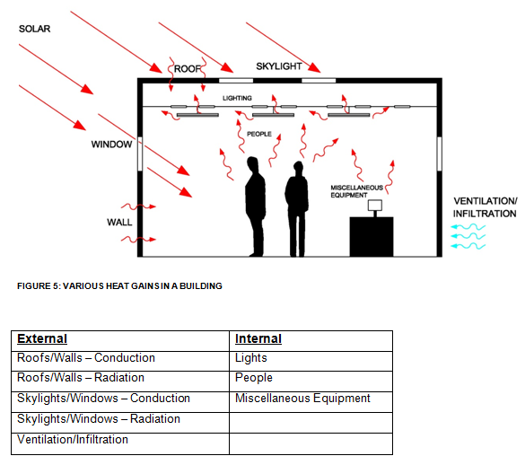
The various heat gains and losses into a building can be characterized as either external or internal loads. External loads include the conduction and radiation heat loads transferred through roofs, walls, skylights and windows. In addition, outside air can be brought into a building through ventilation requirements or infiltration, which will cause a load upon the system. Internal loads include heat loads from people, both latent and sensible, loads from lighting and miscellaneous equipment like computers, televisions, motors, etc.
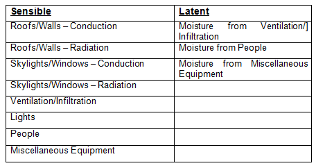
The various heat gains can also be organized into sensible and latent heat gains. Sensible heat gains are those characterized by only a change in temperature and no change in state. Latent heat gains are those characterized by moisture gains. It is important to note that in the table below, that ventilation, infiltration, people and miscellaneous equipment both have sensible and latent heat gains. These individual heat gains are discussed thoroughly in the following sections.
THERMAL MASS and TIME LAG FACTOR
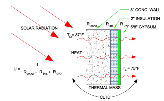
When completing load calculations it is important to understand the time lag factor. When the sun shines upon a wall face early in the morning, although the wall does experience a heat load, the amount of heat load experienced IN the building at that time is minimal. This is due to the thermal mass of the wall. Thermal mass is also known as heat capacity and is defined as the ability of a material to absorb heat.
The use of thermal mass is shown in buildings that have high thermal mass walls that absorb heat during the day, store the heat during occupied periods and release the heat during the night when it is cool.
UNCERTAINTY
Calculating heat gains and determining cooling loads has very high uncertainty. This is because of the many assumptions that must be made like occupant loads, occupant, schedules, outdoor weather conditions, equipment schedules and heat gains, etc. The engineer should recognize that the following calculations are not the most accurate ways to calculate cooling load and are only shown to highlight concepts that could be tested on the professional engineering exam. There are multiple methods used to calculate cooling load calculations like the Radiant Time Series, Total Equivalent Time Difference and the CLTD/SCL/CLF methods. The CLTD/SCL/CLF method is shown in this section because it is the most practical method that can be tested without a computer and in a relatively short period of time (4-hours, 6 minutes per problem).
Cooling Load Calculations - Roof/Wall
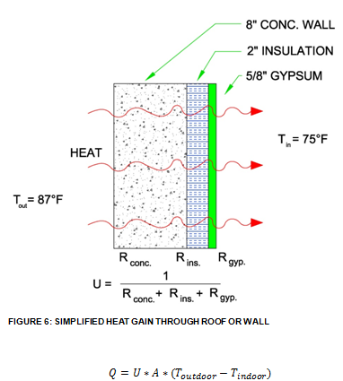
The loads from the roofs and walls are conductive loads. Heat from the outdoors is conducted through the roofing or wall materials as it enters the space. If the problem assumes no radiation loads or does not take into account time, then the only load is the conductive load from the temperature difference between the outdoors and indoors, which is as shown below.
However, the heat effect from the roofs and walls is not this simple. The radiation from the sun onto the building and the time it takes for the heat to transmit through the materials must be taken in to account. In order to calculate the total effect of the difference between the indoor and outdoor temperature, the effect of the solar radiation onto the walls and roofs and the time factor due to the heat storage of the roof/wall material, the engineer should use the Cooling Load Temperature Difference or CLTD. These values can be found in the ASHRAE Fundamentals book 1997 edition and older. These tables are organized by latitude, roof or wall type, month and wall facing orientation direction. In addition, the CLTD is organized by the hour of the day. It is not the opinion of the author that you will need to look-up these values in ASHRAE 1997 and that these values will be given to you as part of the problem. It is only important to understand what CLTD is and how to use it when given it in a problem.

It is also important to note that the CLTD is a simplified approach to determining the heat load due to roofs and walls. In actuality the heat load due to the roofs/walls will also be dependent on many other conditions like the indoor conditions and the heat radiated from the inner wall/roof to the indoor space.
Cooling Load Calculations - Skylight/Window
The heat loads form the skylights and windows can be broken up into (2) types of loads, conductive and radiation loads. The conductive loads for skylights and windows use the same formula as that of the roofs and windows, shown below again.
Conductive loads

The radiation loads or solar transmission is calculated by multiplying the area of the window or skylight by the shading coefficient and the solar cooling load factor.

The shading coefficient is the ratio of the specific window or skylight's solar transmission compared to 1/8" clear glass. The shading coefficient is typically specific to the glass manufacturer and can be found in the manufacturer's product data. During the exam, this value along with the solar cooling load factor should be given. The solar cooling load factor is given in the ASHRAE 1997 Fundamentals book and similarly to CLTD it serves as a simplified approach to calculating heat gain. In addition, SCL is organized similarly by skylight/window, orientation, month, latitude and hour.
In lieu of SC, the term Solar Heat Gain Coefficient (SHGC) is being used by window/skylight manufacturers. This term is simply found by dividing the SC by 1.15. A lower SHGC or SC means that the glass lets in less solar gain and a higher SHGC or SC means that the glass allows more solar gain through.
The National Fenestration Rating Council (NFRC) rates glass and certifies the SHGC and U-Factor. Additional values like Visible Transmittance, Air Leakage and Condensation Resistance are also tested and certified.
Cooling Load Calculations - People
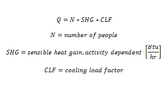
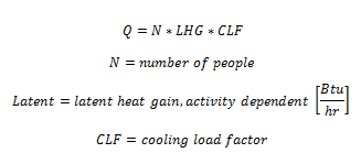
The heat loads from a person depend on the activity level of the person. ASHRAE has tabulated heat loads both sensible and latent heat gains from people based on their activity levels, refer to ASHRAE Fundamentals. The loads from people can be calculated using these heat gain values, the number of people and the cooling load factor, as shown in the equations below. The cooling load factor takes into account the time lag factor and if it is not given it should be assumed to be 1.0.
Sensible loads
Latent loads
R-Value stands for thermal resistance and it is representative of a material’s ability to resist heat. This is opposite of the U-Factor and thermal conductance which are measures of a materials ability to conduct heat. The relationship between the R-Value, U-Factor and thermal conductance is shown in the following formula.
Cooling Load Calculations - Lighting
The heat load from lighting in a building is found by summing up the number of lights of each type and wattage, then converting the watts to Btu/hr, multiplying this number by the usage factor and the special allowance factor, as shown in the below equation.
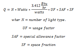
The wattage of the light is based on the manufacturer reported value for the lamps in the lighting fixture, without taking into account the ballast. The lighting use factor is the ratio of the time the lights will be in use. This factor is typically 1.0 for most applications like offices, classrooms, stores, hospitals, etc. The usage factor may vary for a movie theater or inactive storage space. The special allowance factor takes into account the heat from ballasts. This factor is typically 1.2 for fluorescent lights and 1.0 for incandescent lights due to the lack of ballasts in incandescent lights.
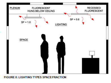
Finally, the space fraction is the fraction of the total heat from the lights that is transmitted to the space. Lights located at the ceiling may have a percentage of its heat transmitted into the plenum and not into the space. This means that the air conditioning system, if the return is ducted, will not see the percentage of the heat that is transmitted to the plenum. If the plenum is used as a return, then the air conditioning will see the total heat from the lighting. For example, the space fraction for a hung fluorescent light (non-ceiling) will be 1.0, because the light is completely into the space. On the other hand a ceiling recessed light could have a space fraction of 0.5, meaning that 50% of its heat is transmitted to the plenum and the other 50% is transmitted to the space.
Cooling Load Calculations - Miscellaneous Equipment
The heat gains from miscellaneous equipment can be found by the following equations.
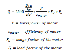
The first equation is used for motors, where P is equal to the nominal horsepower of the motor. Dividing the horsepower of the motor by the efficiency of the motor allows the heat gains due to the motor and the heat gains due to the inefficiency of the motor to be taken into account. If the motor is used continuously then the usage factor will be 1.0. Otherwise the usage factor will be the fraction of the time that it is used divided by the total time the space is occupied. The load factor of the motor takes into account the fact that motors rarely run at its nominally rated capacity. For example, if a 1 HP motor actually operates at 0.75 HP then the load factor will by 0.75.
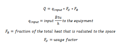
The second equation describes heat gain from everyday appliances like microwaves, toasters, ranges, ovens and computers. The input energy is found by researching the manufacturer's product data or by referring to typical values reported in ASHRAE Fundamentals. ASHRAE Fundamentals also has typical usage factors and radiated heat fractions for typical equipment. Also shown in ASHRAE Fundamentals are the sensible heat gains for typical pieces of equipment, which bypasses the formula below.
Cooling Load Calculations - Infiltration
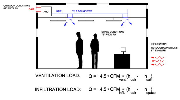
Infiltration is described as outside air that leaks into a building structure. These leaks could be through the building construction or through entry doors. Infiltration heat gains are found by the following equations. These equations are discussed more in the Psychrometrics Section.
The first equation is the total heat gains using enthalpy. In this equation, the volumetric flow rate of the infiltration or ventilation air must be known. This value is converted and multiplied by the difference in enthalpy between the outdoor air conditions and the indoor air conditions.

The following two equation split the total heat gain into the sensible and latent heat loads.
Sensible Heat Gains are calculated by multiplying the CFM of the infiltrated air by the difference in the temperatures of the indoor and outdoor air.

Latent Heat Gains are calculated by multiplying the CFM of infiltrated air by the difference in the humidity ratio of the indoor air and the outdoor air.

It is important to note that these loads are not seen directly by the cooling coil. These are indirect loads that occur in each air conditioned space. Ventilation air is seen directly at the coil and thus this air must be cooled down to the supply air distribution temperature which is much lower than the room condition air.
