Engineering Pro Guides is your guide to passing the Mechanical & Electrical PE and FE Exams
Engineering Pro Guides provides mechanical and electrical PE and FE exam technical study guides, practice exams and much more. Contact Justin for more information.
Email: contact@engproguides.com
EXAM TOOLS
Systems & Components (18 of 80 Problems)
Introduction
This section of the exam guide book focuses on the Mechanical Systems used in the HVAC & Refrigeration field. The systems and components section accounts for approximately 18 questions on the HVAC & Refrigeration Mechanical PE exam.
The systems discussed in this section include the most common systems that are on the PE exam. The previous section described the equipment that make up these systems in more detail. Also at the end of this section is a brief discussion on controls.
Air Distribution Systems: The air distribution systems consist of an air handler (coil and fan), ducting, air, and terminal devices.
Fluid Distribution Systems: A fluid distribution system consists of a pump, piping and the fluid.
Refrigeration Systems: Refrigeration systems are primarily used to cool and freeze food.
Energy Recovery: Energy recovery systems are additions onto an air distribution or fluid distribution system that make the air or fluid distribution system more efficient.
Air Distribution
In the HVAC field, air distribution systems are used to supply cold/hot air to various spaces to keep the occupants comfortable and/or to keep equipment at optimum conditions. Fresh air is also provided through the air distribution system to provide appropriate ventilation levels, in order to alleviate carbon dioxide (CO2) levels.
An air distribution system consists of a supply air system, return air system, outside air and exhaust air system. The supply air system consists of an air handling unit, supply ducting, dampers, terminal units and diffusers. An air handling unit is a fan with cooling/heating coils. The air handling unit cools/heats supply air and then distributes it through the ducting system, which consists of ducts, dampers and duct fittings. Once the air reaches the space, it is then directed to a terminal unit, which controls the amount and conditions of air distributed to that specific space. Next the air is delivered to the space through a supply air diffuser, this piece of equipment controls the way the air is distributed throughout the space. The return air system consists of return air registers, ducts, dampers and duct fittings. The return air system also exhausts air via the exhaust air system, before sending the return air back to the air handler, where the cycle begins again. At the air handling unit, the exhaust air is replaced with new outside air.
Air Supply Ducts
In the HVAC field, air distribution systems are used to supply cold/hot air to various spaces to keep the occupants comfortable and/or to keep equipment operational. Fresh air shall also be provided through the air distribution system to provide appropriate ventilation levels, in order to alleviate carbon dioxide (CO2) levels.
DUCTS
The method in which air is routed throughout a building is through the use of ducts, which can be constructed of metal, plastic or fiberglass. As a minimally competent engineer, one should be able to accomplish the following:
1) Determine the velocity in ducts.
2) Determine the pressure drop in ducts.
3) Size the duct based on required velocity or pressure drop.
Darcy Weisbach Equation
The equation used to determine the pressure drop in ducts is the Darcy Weisbach Equation.
Converting to more commonly used HVAC and Refrigeration units:
Although this equation is the governing equation for determining pressure drop, it is most often not used in the HVAC and Refrigeration field. In this field, airflow pressure drop calculations through are completed through the use of Friction Charts. Airflows, pressures, elevations and duct construction NOT normally encountered in the HVAC and Refrigeration should use the Darcy Equation.
Determining Velocity in Ducts for Pressure Calculations.
In the HVAC and Refrigeration field airflow is typically measured in cubic feet per minute or CFM. But velocity is the term that is required in determining the pressure drop of the air flow through a duct. In order to determine the velocity, the area of the duct must be found. Finding the area of ducts is a simple calculation for circular ducts, which are shown below.
For rectangular and oval ducts, the area CANNOT be calculated as shown below. The rectangular and oval duct dimensions MUST FIRST be converted to Equivalent Diameter. Remember, that the pressure loss calculations require a circular shape.
Determining Diameter of Duct
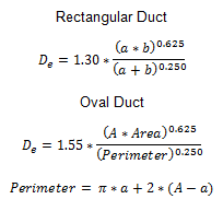
The Friction Charts and the Darcy Equation are typically a function of duct diameter. Thus no calculations are necessary for a circular duct. However, rectangular and oval ducts must be converted to an equivalent diameter circular duct before the equation can be properly completed. The equations for determining equivalent diameters are shown below.
A quicker way to determine equivalent diameter is to use the Equivalent Diameter Tables for Rectangular and Oval ducts shown in ASHRAE Fundaments.
Determining Pressure Drop in Ducts
Once the equivalent diameter of the duct is found and the CFM is known, then simply refer to the Friction Charts for Ducts and simply read the pressure drop. This process is detailed more in Fan Sizing, later on in this section.
Air Devices
Diffusers, registers and grilles are at the end of ducts and serve as the distribution equipment to the conditioned space. The purpose of these mechanical pieces of equipment is to provide thermal comfort for the occupants of the space or to provide proper thermal conditions suitable for the equipment in the space.
Diffusers are defined as air terminal devices that distribute conditioned air in various directions through the use of its deflecting vanes. It is designed to promote the mixing of conditioned air with the air already in the space. It is important to properly mix the conditioned air into the space, in order to provide cooling/heating and to distribute fresh air to the entire space and to avoid stagnant air in the space. However, not all types of diffusers have the same performance in mixing the conditioned air in the space. Each diffuser will be provided with a table describing its performance similar to the one on the following page.
The values shown in tables similar to the one above are specific to a certain manufacturer’s type of diffuser and size. The third row indicates the total amount of CFM that is distributed through this diffuser. This term is the value with which the designer will begin. From this value, the velocity and pressure drop through the diffuser can be determined. It is also important to note that at higher velocities, the pressure drop increases and the NC or noise criteria increases. The NC rating corresponds to a curve of DB levels at various frequencies. This NC rating is used to rate the sound levels of air conditioning equipment and also used to rate the sound requirements of rooms. For example, a typical classroom will require a NC rating of 25-30. Using the table above, this corresponds to a maximum airflow somewhere between 85 and 95 CFM.
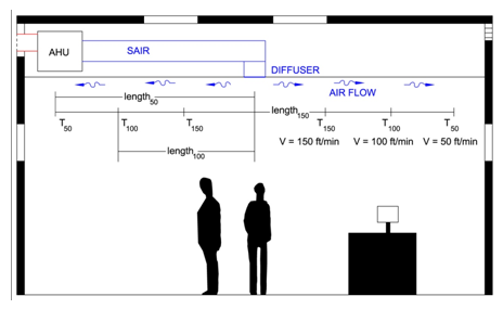
Throw is defined as the horizontal distance from a diffuser at a specified velocity. For example, T50 = 15’, indicates that at a distance of 15’ from the diffuser, the velocity of the air will be 50 feet per minute. T100 = 10’, indicates the distance at which the air velocity is 100 feet per minute and T150 = 5’, indicates the distance for 150 feet per minute. Often times throw is shown simply in the following format, [T150 -T100 - T50]. For example, in the table above an airflow of 60 CFM results in a velocity of 150 fpm at 7’ from the diffuser, a velocity of 100 fpm at 9’ from the diffuser and a velocity of 50 fpm at 12’ from the diffuser. Refer to the following figure for a graphical explanation.
Typically in diffuser layout design for occupied areas, it is required to locate diffusers so that the T50 length is nearly equivalent to the characteristic length. The characteristic length is defined as the distance by one of the following:
1. Perpendicular distance between the center line of the diffuser and the wall.
2. Midpoint between the centerline of two diffusers.
Grilles are defined as air devices that consist of an opening with a covered grating or screen. Grilles are often used to return air back to the fan or to exhaust air from a space. Grilles are not typically used to supply air because there is an inability to accurately control the amount of air being supplied.
Registers are simply grilles with a damper that is used to restrict the amount of air flow required to be returned, supplied or exhausted.
Fluid Distribution
In the HVAC & Refrigeration field, fluids are distributed throughout various types of systems, like chilled water, hot water, condenser water, condensate systems, fuel compressed air and steam. These systems have three things in common, (1) piping, (2) pumps and (3) liquids.
(1) Piping is used as the means to transfer the liquid from one point to the next. It is important to be able to (a) determine the pressure drop through a piping system and (b) determine the velocity of liquid through a pipe. These skills will be discussed as part of this section.
(2) Pumps are used to provide the necessary mechanical energy to move a desired liquid flow rate at the desired pressure. The important pump skills consist of (a) selecting the appropriate pump, (b) determining the necessary volumetric flow rate, (c) determining the total dynamic head and (4) determining the net positive suction head available. All of these items are discussed in this section, except determining the volumetric flow rate, which is dependent on the amount of energy that is required and has already been discussed in multiple areas.
(3) The properties of liquids that are important have been discussed in the fluids section.
Total Pump Head
In order to properly select a type of pump, the engineer must know which type is most applicable to the situation. Sizing a pump depends on two criteria, (1) the flow rate and the (2) total dynamic head. The flow rate is determined by the needs of the HVAC and Refrigeration system. The pump may be a chilled water pump serving several air handlers, so the flow rate (GPM) can be found by adding up the design flow rates to the air handlers and any diversity required. The (2) second criteria is the total dynamic head. Determining total head is a must-have skill for the aspiring professional engineer.
Pump Selection:(1)GPM and (2)TDH [total dynamic head]
Total head or total dynamic head is the total equivalent height of water that a fluid must be pumped against.
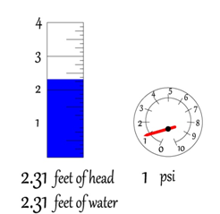
Head is a unit of pressure and has the units of feet of head, which is the total pressure exerted by a certain amount of feet of a water column.
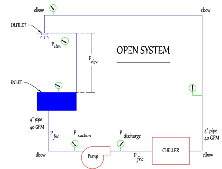
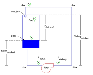
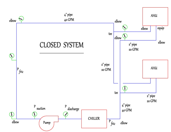
Total head can be broken up into the following components, (1) Static head or Elevation Difference between the inlet and the outlet of a piping system (2) Friction loss. In a closed system, both static (elevation) head and friction loss are present. However, in a closed system there is no elevation difference, the beginning and the end of the piping system are the same, therefore there is no elevation difference. Refer to the following figures, which describe the different pressure losses in a open and closed system./
The typical example of an open system in the HVAC and Refrigeration field is the condenser water system serving a cooling tower. The pump moves the condenser water from the cooling tower basin through piping, then the chiller and back to the top of the cooling tower. The pump must provide a total dynamic head to account for the (1) Static [Elevation] head and (2) the Friction Head through the piping, chiller, fittings, other equipment and appurtenances.
(1) The static head is the difference between the inlet and the outlet. The elevation difference between the inlet and the pump, on the suction side of the pump is called the suction static head and the elevation difference between the outlet and pump, on the discharge side is called the discharge static head. The difference between discharge and suction static head is the static/elevation head that the pump must pump against.
(2) Friction head. Friction head consists of pressure losses due to equipment like chillers, cooling towers, filters, strainers, heat exchangers, air handlers, etc. The amount of friction head from these pieces of equipment are provided by the manufacturer and are typically provided in a table format with total friction head or pressure loss for the equipment versus the flow rate. Friction head also consists of pressure losses due to the piping and the various fittings like elbows, tees, valves, etc. Calculating friction had due to piping will be discussed later in this section.
The typical example of a closed system in the HVAC and Refrigeration field is the chilled water system serving the air handlers and chillers. The pump moves chilled water to and from the chiller and through the air handlers. The pump must provide a total dynamic head to account for only the Friction Head through the piping, chiller, fittings, other equipment and appurtenances. There is no static/elevation head because the system is closed.
Friction Loss: Friction loss is found through the use of either the Darcy Weisbach equation or the Hazen-Williams equation. The Darcy Weisbach equation is slightly more involved and will be explained below, starting with the equation.h
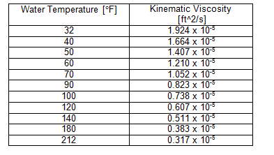
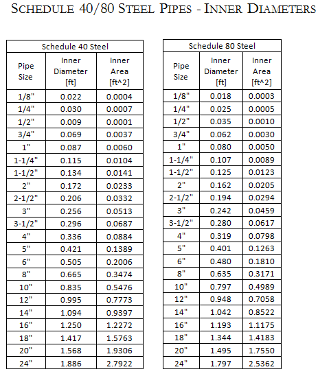
During the exam, in order to quickly complete a friction loss question using the Darcy Weisbach, the aspiring professional engineer must have the necessary tools readily available to find the values necessary to complete the equation. These include the following, 1) Inner Diameter tables of common pipe materials and sizes, 2) Flow unit conversions, 3) Inner Area table of common pipe materials and sizes, 4) Kinematic viscosity tables of common fluids at various temperatures and 5) the Moody Diagram.
1) Inner Diameter Table of Common Pipe Materials
Collect inner diameter [ft] tables of schedule 40/80 steel [Pipe sizes to 30"], type K, L, and M copper tubing [Pipe sizes to 6"] and schedule 40/80 PVC [Pipe sizes to 30"]. Provide inner diameters in feet for ease in using the Darcy Weisbach Equation.
2) GPM to FT^3/sec Conversion Factor
Multiply GPM by 1/448.83 to get (FT^3)/sec.
3) Inner Area Table of Common Pipe Materials
Collect inner area [ft^2] tables of schedule 40/80 steel [Pipe sizes to 30"], type K, L, and M copper tubing [Pipe sizes to 6"] and schedule 40/80 PVC [Pipe sizes to 30"]. Provide inner areas in feet^2 for ease in finding the velocities through the pipes.
4) Kinematic Viscosity Tables [used to get Reynolds number which leads to the friction factor]
5) Pipe Roughness
Collect pipe roughness factors for common pipe materials, steel, PVC, copper, etc.
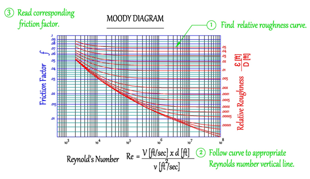
6) Moody Diagram: The Moody diagram uses the Reynold's number and the relative roughness factor to determine the friction factor. The relative roughness factor is found by first finding the roughness value corresponding to the pipe material. Then dividing the roughness factor by the inner diameter of the pipe. Ensure that the roughness factor and the diameter are in the same units. The Reynold's number is found by multiplying the velocity of the fluid through the pipe by the diameter of the pipe and dividing by the kinematic viscosity of the fluid. Once these two values are found (a) Relative Roughness and (b) Reynold's Number, then the friction factor can be found by finding the intersection of the vertical Reynold's number line shown in black and the Relative Roughness factor curves shown in red.
Step 1: Find relative roughness factor, step 2: find intersection of reynold's number and relative roughness factor. step 3: read corresponding friction factor.
Net Positive Suction Head
The professional engineer must be able to properly determine net positive suction head in order to avoid cavitation. Cavitation occurs when the suction pressure (head) is less than the vapor pressure of the water. If the suction pressure is lower than the vapor pressure, then small vapor bubbles form and when these bubbles reach the pump where the pressure is increases, the bubbles implode causing damage to the impellers and other parts of the pump. This is what is known as cavitation.
Suction head is defined as the pressure at the inlet of the pump and net positive suction head is the difference between the suction head at the inlet and the vapor pressure of the water at the inlet of the pump.
Net Positive Suction Head Available=Suction Head_(inlet of pump)-Vapor Pressure_water
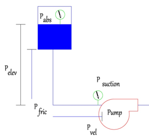
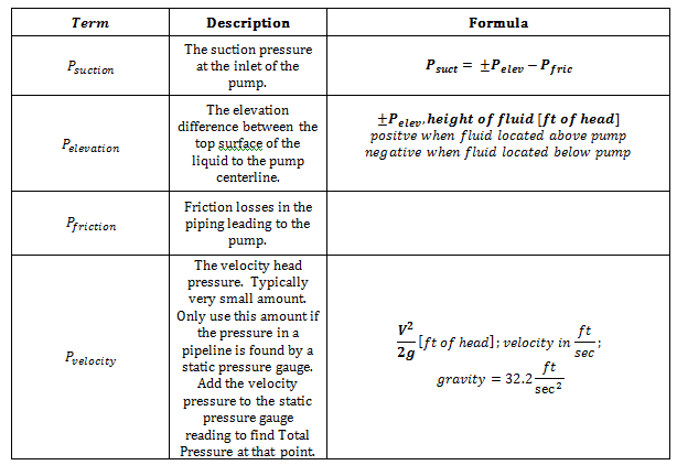
Net positive suction head is the total amount of head or pressure at the inlet of the pump. This value is found by determining all the pressures acting upon the fluid whether positive or negative. The following figure best describes all the pressures that can be acting upon a pump.
(1) P_abs: This pressure refers to the absolute pressure acting on the fluid. If the tank is pressurized, then the value is pre-determined. If the tank is open to the atmosphere, then the pressure is equal to 1 atmosphere [atm] or 14.7 psia or 33.9 ft of water.
(2) P_elev: This pressure identifies the elevation difference between the top surface of the liquid and the pump centerline. This value can be positive or negative and is measured in ft of head.
(3) P_fric: The friction pressure or head is the amount of pressure lost due to friction in the piping, fittings, equipment, valves, etc. leading from the fluid source to the pump.
(4) P_vel: The velocity head pressure is the pressure due to the flowing liquid.
(5) P_suction: Finally, all of the pressures leading to the pump are summed and the resulting value is the suction pressure at the pump.
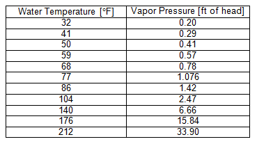
The vapor pressure of the water is found by simply looking up water (or pumping fluid) tables and finding the vapor pressure at the operating temperature. In the HVAC and Refrigeration field, water is the most common fluid used in pumping systems and a table of corresponding vapor pressure and temperatures are shown below.
From the table above, it can be seen that as the temperature of the water increases, the pressure at which vaporization will occur also increases. Thus cavitation becomes even more critical at higher temperatures.
Refrigeration
In the HVAC & Refrigeration field, you may encounter the task of cooling and freezing food. On the exam, these types of problems involve finding the relevant properties of food, then calculating the time to cool and freeze the food. For these types of problems, you should have your ASHRAE Refrigeration book and specifically turn to the thermal properties of food chapter.
Cooling and freezing food involves first cooling food to its freezing point, then removing the latent heat of fusion, followed by cooling the food to the final desired temperature.
The first step is to use the specific heat of the food to calculate the amount of cooling required to bring the temperature of the food down to the freezing point. Make sure to use the correct specific heat, because the specific heat does vary based on whether or not the food is frozen.
The second step is to use the latent heat of fusion, H_fusion, which can be found in the ASHRAE Refrigeration Handbook. This is the amount of energy required to change the phase of the liquid parts of the food to a solid, since some of the food consists of oils and water.
The third step is to use the specific heat of the food to calculate the amount of cooling required to bring the temperature of the food down from the freezing point. Make sure you use the correct specific heat, because the specific heat does vary based on whether or not the food is frozen.
The above equations determine the amount of BTU required to cool food from one temperature to a temperature below freezing. Often times, food must be frozen within a certain amount of time. In order to determine the amount of time it takes for the above process, you must use the cooling power, P_Refrigeration (Btu/Hr), of the refrigeration system and the total cooling required with the following equation.
Energy Recovery Devices
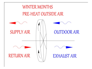
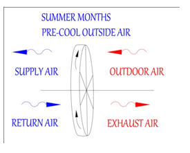
An energy recovery device is an air to air heat exchanging device. In the HVAC and Refrigeration field, energy recovery devices are used to exchange energy from outgoing exhaust air to incoming outside air. During the winter months the outside air is pre-heated prior to entering the air handler and during the summer the outside air is pre-cooled.
Energy recovery devices are governed by the following equations.
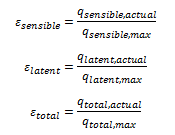
The effectiveness of an energy recovery device is defined as the ratio of the actual heat transferred to the maximum amount of heat that can be transferred. The effectiveness can be rated in terms of sensible heat transfer, latent heat transfer or total heat transfer.
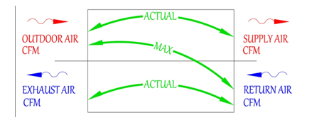
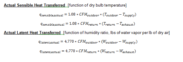
The actual amount of energy transferred is found by multiplying each individual airstreams mass flow rates by the change in conditions, whether it is a change in temperature, change in humidity or change in total enthalpy.
The maximum amount of energy transferred is met if the entering condition of the 1st air stream exits the energy recovery device at the same conditions as the entering condition of the 2nd air stream. However, if one airstream has more air flow than the other, then the smallest airstream should be used.
There are various types of energy recovery devices listed below:
Rotary Sensible Wheel
A rotary sensible wheel is typically a metal wheel that rotates and exchanges heat from one air stream to another. The wheel is connected to a gear and motor, which rotates the wheel. As a section of the wheel picks up heat from air stream, the wheel then rotates to the other air stream to move the heat to the cooler air stream.
Rotary Enthalpy Wheel
A rotary enthalpy wheel is similar to a rotary sensible wheel, in that it has the same type of construction and parts. But in addition, a rotary enthalpy wheel has a desiccant material that is used to absorb moisture. A section of the wheel absorbs moisture from the more humid air stream, then rotates and transfers the moisture to the more dry air mixture.
Wrap-Around Heat Pipe
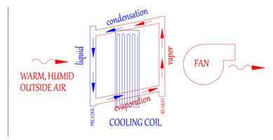
A wrap around heat pipe is used typically in warm humid climates in spaces with a high amount of outside air requirements. In these types of environments, warm, humid outside air is conditioned to a low temperature in order to condense the water out of the air. A wrap-around heat pipe is used to pre-cool the incoming warm humid outside air by transferring heat to the exiting cool supply air. This has the effect of providing sensible re-heat to the supply air, which also decreases the need for additional re-heat.
The heat pipe contains a pressurized refrigerant, which proceeds through the vapor compression cycle with the design temperatures. In the first phase, warm air passes over the cool liquid refrigerant. This effectively pre-cools the outside air before it enters the main cooling coil. During this first phase, the liquid refrigerants gains heat, causing it to vaporize and move to the other side of the coil. In the second phase, on the other side of the coil, the cool air passes over the warm vapor, which re-heats the air. In addition, the warm vapor is condensed to a liquid, allowing the process to start over again.
In this example, energy is transferred in the same air stream from the entering outside air to the existing supply air. The heat pipe can also be used to transfer energy between two different air streams. For example, it can be used between the outdoor/supply air and the return/exhaust airstreams.
Run-Around Loop
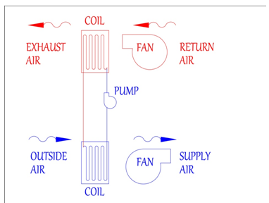
The last energy recovery device that is explained in this section is the run-around coil. The run around loops consists of two heat exchange coils connected by piping, a fluid and a pump. A heat transfer fluid, typically water or a glycol-water mixture is pumped between the two coils. The fluid transfers heat from one air stream to the other air stream.
Econimizers
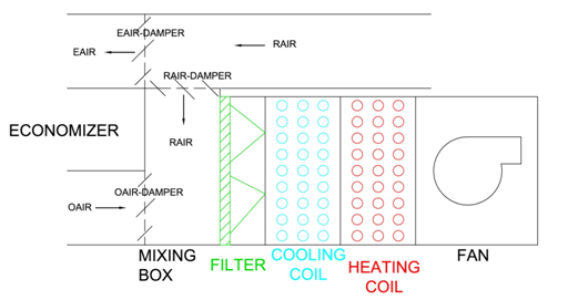
An economizer is another means of energy saving. In its simplest form it consists of two sets of dampers, one set controlling the amount of return air that is directed either to exhaust or back to the air handler and a second set controlling the amount of outside air routed to the air handler.
Cooling Season: When the outside air (OAIR) has a lower enthalpy than the return air (RAIR), then the OAIR is directed to the coils and the RAIR is routed to the exhaust. By routing the lower enthalpy air (OAIR), the coil requires less energy to provide cooling. If the enthalpy of the RAIR is lower than the OAIR, then the RAIR is routed to the coil and only the minimum amount of OAIR is routed to the coil. OAIR is still required in order to maintain the proper amounts of fresh air to the occupants.
Basic Control Concepts
The sub-field of controls in HVAC & Refrigeration is very vast and can span many different topics. Luckily, only the basics are required for this section on the HVAC & Refrigeration PE exam. Since, there should only be a few questions on controls, you will want to limit the amount of time you spend on studying controls. You should know the following for the exam.
1. Control System Fundamentals- Analog vs. digital control
- What is PID?
- Digital input and analog input sensors (temperature, pressure, flow, CO2, humidity, etc.)
- Digital output and analog output devices (actuators, valves, dampers, etc.)
- Types of controllers
- VAV cooling
- VAV cooling with reheat
- Economizer cycle
- Heating control from supply air
- Control of chilled water coil with 3-way valve
- Two position control of direct expansion coil
The best resource for studying controls for the exam is the free Honeywell white paper called, Engineering Manual of Automatic Control for Commercial Buildings. It can be found on the link below. It is over 500 pages long. Please read briefly through the entire white paper and have it as a reference during the exam. You should pay special attention to the following sections, Control Fundamentals, Microprocessor-Based/DDC Fundamentals and Control System Applications. Do not spend time on the Pneumatic, Electric and Electronic Controls sections. These are outdated versions of control in the HVAC field. These methods of control may still be used in other applications. https://customer.honeywell.com/resources/techlit/TechLitDocuments/77-0000s/77-E1100.pdf


