![]()
Engineering Pro Guides is your guide to passing the Mechanical & Electrical PE and FE Exams
Engineering Pro Guides provides mechanical and electrical PE and FE exam technical study guides, practice exams and much more. Contact Justin for more information.
Email: contact@engproguides.com
DESIGN
HVAC Rule of Thumb Calculator
Section 1.0: Introduction
During the early stages of HVAC design, it is important to be able to quickly determine the overall size of an HVAC system in order to assist the owner and/or architect space plan and determine rough costs. At these early stages, the space changes very quickly and the owner and/or architect need immediate feedback to be able to ensure that there is adequate space for mechanical equipment and there is sufficient funds.
It takes years of experience to be able to quickly select an HVAC system type, size the HVAC system and cost the HVAC system, with limited information. After designing a multitude of HVAC systems for all sorts of buildings, you should be able to
The calculator uses the building square footage, building usage type and building shape to automatically determine the maximum and minimum overall tonnage and electrical usage of the equipment for multiple HVAC systems. The HVAC systems analyzed in this calculator include (1) split systems/packaged A/C, (2) air cooled chilled water systems and (3) water cooled chilled water systems. This will help you to select equipment, space plan for any mechanical rooms and ceiling space and create a budget. Also by providing electrical values for the equipment, the electrical engineer can also plan for utility service, transformers and panels.
Section 1.1: Disclaimer
In no event will Engineering Pro Guides be liable for any incidental, indirect, consequential, punitive or special damages of any kind, or any other damages whatsoever, including, without limitation, those resulting from loss of profit, loss of contracts, loss of reputation, goodwill, data, information, income, anticipated savings or business relationships, whether or not Engineering Pro Guides has been advised of the possibility of such damage, arising out of or in connection with the use of this document/software or any referenced documents and/or websites.
Section 2.0: Units
There are two calculators, (1) one that focuses on United States Customary System Units (USCS) and another on (2) International System of Units (SI). However, this guide focuses exclusively on the USCS.
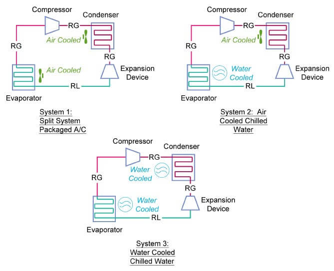
There are two main sets of units that should be discussed in more detail, (1) EER and (2) SEER. First, you need to understand that the efficiency of air conditioners in the refrigeration cycle is greatly dependent on the heat rejection provided at the evaporator and condenser. In the first figure, you can see that the heat rejection at the evaporator and condenser change from air to water as you move from split system to water cooled chilled water system. This change in heat rejection from air to water greatly improves the efficiency because the heat transfer is much better with water due to its increased heat capacity.
EER: The Energy Efficiency Ratio or EER is the ratio of the total cooling or heating Btu/h to the total input power in watts. The conversion from EER to kW/ton is shown below. The amount of cooling or heating provided is a function of the outdoor and indoor conditions. For cooling EER calculations, all manufacturers' equipment are tested at 95 F DB outdoors and 80 F/50% RH indoors.

SEER: The Seasonal Energy Efficiency Ratio or SEER is similar to EER, except manufacturers' equipment are tested at multiple conditions for various seasons.
Section 3.0: How to use the HVAC Rule of Thumb Calculator
This book should be used in conjunction with the excel spreadsheet titled HVAC Rule of Thumb Calculator. This book provides you more background knowledge on inputs (Section 4.0) and understanding and interpreting the outputs (Section 5.0).
When using this calculator, first you should enter your building inputs. These inputs are the minimum amount of information necessary to produce a reliable analysis on your HVAC requirements. There are certain inputs that are from a drop down menu and contain only a set amount of options. If you feel that your building cannot be characterized by one of the options, then you can override the drop down menu. Please only override the option after reading this manual in order to understand how each input affects your analysis.
Second, you need to choose your system type. The available options for system types are (1) split system, (2) air cooled chilled water and (3) water cooled chilled water. There is more description on each of the system types. Your system type may not exactly fit one of these three system types, due to the many variations in HVAC system types. However, the system types and this calculator are only used to calculate overall sizes of major HVAC equipment. You may have variations like an energy recovery system or a reheat system that are not included, but the main equipment will be accounted for in this calculator.
Finally, you need to read and interpret your results. The results are meant to guide space planning and budgeting during the initial stages of design. The results can also be used to double check a preliminary or final design to ensure the design falls within the ranges presented in the calculator. A design that occurs outside of the range may be a sign of a significant problem in the design. These results are not meant to finalize or to purchase equipment. A complete and detailed calculation should be conducted to get more exact results for these purposes.
Section 4.0: Selecting the Inputs
Section 4.1: Building Information
The first step in using the HVAC Rule of Thumb Calculator is to input the building information like the building air conditioned area, building type, building shape and building location. Each of these options will be discussed in further detail in this section.
Section 4.1.1: Building Area
The building area is not the total area, but only the area of the building that will be air conditioned. For example, mechanical/electrical rooms, bathrooms, storage rooms are often not air conditioned. Non-air-conditioned areas should be excluded from the building area input.
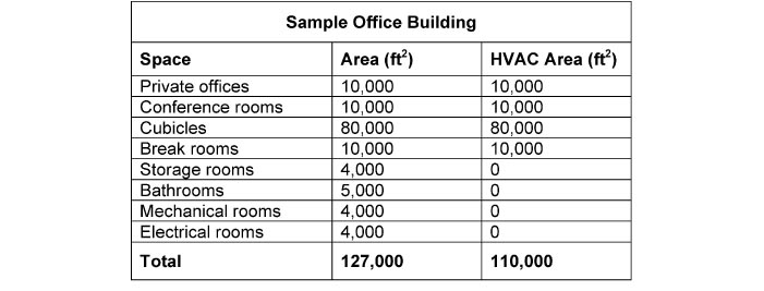
In the sample office building above, you would use the 110,000 ft2 value in the HVAC Rule of Thumb Calculator.
Section 4.1.2: Building Types
The building type is used to provide the appropriate square foot per ton value and airflow (CFM) per square foot value.
Apartment, Mid/High Rise
Description: This building type can be used for apartments or condominiums that are larger than single family homes or multi-family dwellings. An apartment building under this type can be a high rise type with more than 10 floors or a mid-rise with 5 to 10 floors. These apartments are often served by a central HVAC system, but can also be served by individual split systems per apartment. The units within the apartment can be studios, one-bedroom and larger units.
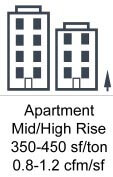
Cooling Load: The higher tonnage and airflow values correspond to apartments in hotter/more humid climates with larger amounts of external fenestration (windows and/or skylights).
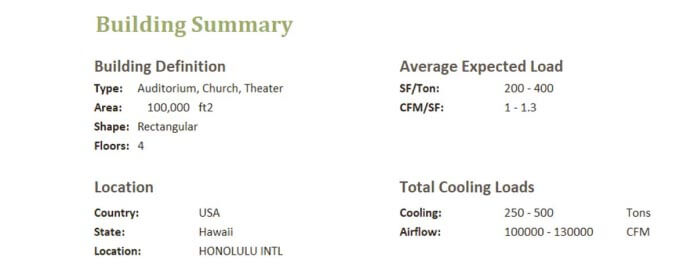
Auditorium, Church, Theater:
Description: Auditoriums, churches and theaters are characterized by a high people density values. These people also have a sedentary activity level. These types of buildings have high people cooling loads and high amounts of outside air requirements. Other assembly areas like cafeterias can also use this building type. Kitchens should not be included in the cafeteria area, because kitchen loads are based primarily on the specific equipment.
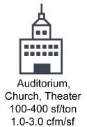
Cooling Load: The higher tonnage and airflow values correspond to buildings that are located in hotter/more humid climates, because the primarily load within these types of buildings will be due to the large amounts of ventilation air required for all the people. The lower tonnage and airflow values correspond to buildings with a higher square foot per person value. Typically, you will not be in the 400 sf/ton range because these types of buildings try to fit as many people as possible. A value in the 250 sf/ton and 1.5 cfm/sf range is most likely.
Elementary, High School, College:
Description: This building type can be used for elementary schools, high school, universities and colleges. Unfortunately, this building type cannot be used for pre-school and child care facilities. This building type is characterized by primarily classroom type spaces with high people density values. There can be ancillary air conditioned spaces like offices and assembly areas within this building type, assuming these spaces do not exceed 20% of the total building area. If you have large office spaces or assembly areas, then break out those areas with a separate calculator.
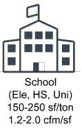
Cooling Load: Similar to the previous entry on assemblies, the higher tonnage and airflow values correspond to buildings with higher square foot per person values and buildings that are located in hotter and more humid climates.
Factory, Industrial:
Description: Factories and industrial type buildings typically have low external loads, low people loads, but high equipment loads. These loads are primarily sensible, which causes higher airflow requirements. There may be small ancillary conference rooms or office rooms that support the building, which you can still include in the area as long as these ancillary spaces do not exceed 20% of the total building area.
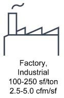
Cooling Load: The higher tonnage and airflow values correspond to buildings with a higher density of equipment that either require fresh air or emit large amounts of heat. The location shouldn’t affect buildings that have minimal fresh air requirements, because these factories and industrial type buildings rarely have fenestration.
Hospital, Medical:
Description: Hospitals and medical facilities consist of primarily patient rooms, doctor’s offices, nurse stations, waiting areas and support ancillary spaces. You should not include surgery rooms or laboratories that require 100% outside air (OAIR). There is another building type for these types of spaces, titled 100% OAIR. Hospital and medical facilities have a lot of specific equipment like warmers and incubators that contribute to the cooling load. In addition, these buildings also require more ventilation to maintain specific air changes rates.
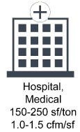
Cooling Load: The higher tonnage and airflow values correspond to buildings with more heat producing medical equipment like a building with MRI machines or birthing rooms as opposed to a dentist’s office which has smaller heat producing equipment. Some medical facilities are also including more fenestration, which will cause higher tonnage and airflow values.
Hotel, Motel, Dorm:
Description: Hotels, motels and dormitories consist of primarily rooms for sleeping. Support ancillary spaces like offices and reception areas are also included in this building area. These buildings also have elevators and are characterized by a high percentage of fenestration. Low rise buildings like walk-up apartments should not be included in this building type. Walk-up apartments should use the residential building type. Restaurants located within these buildings can use the Shops building type.

Cooling Load: The higher tonnage and airflow values correspond to buildings with more heat producing medical equipment like a building with MRI machines or birthing rooms as opposed to a dentist’s office which has smaller heat producing equipment. Some medical facilities are also including more fenestration, which will cause higher tonnage and airflow values.
Library, Museum:
Description: Libraries and museums consist of spaces with large open areas and most often minimal fenestration. These spaces have stricter temperature and humidity control in order to maintain the condition of the exhibits and books. The spaces also typically have more area dedicated to exhibits and books, which leaves less space for people. There is also minimal heat producing equipment in these spaces.

Cooling Load: Higher tonnage and airflow values correspond to buildings that can accommodate more people. For example, a building with few exhibits like an art gallery will have less space dedicated for non-heat producing exhibits, but more space for people. The increased number of people will increase the cooling loads. Sometimes, these buildings will have a higher percentage of fenestration on its external structure, which will also increase the cooling load towards the higher end of the range.
Office:
Description: Offices are characterized by cubicle spaces with one person for about every 140 square feet. Each cubicle typically has one computer and one screen. Private offices and ancillary support spaces like conference rooms and break rooms are also included in the building area. Large employee cafeterias that exceed 20% of the total building area should not be included in the building area.
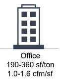
Cooling Load: Higher tonnage and airflow values correspond to buildings that have higher computing loads and higher people loads. Some office buildings have employees with multiple screens and less area per person. An example of this type of building could be a government command center. Other office buildings can also have higher percentages of fenestration that will cause higher loads or large printers and copiers can also cause higher loads.
Residential:
Description: The residential building type encompasses small and large single family homes. Also included are walk-up type apartments that are in the range of 1-5 floors. These buildings have minimal equipment loads like televisions and computers. Ovens and stoves that are only occasionally operated, typically do not affect the design cooling load. Small laundry rooms and common areas can also be included in the building area, as long as these areas do not exceed 20% of the total building area.
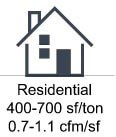
Cooling Load: Large single family homes and apartments with high fenestration percentages on the external façade will have tonnage and airflow values towards the higher end of the range.
Servers, Computers, Electronics:
Description: These types of spaces are primarily for buildings with large amounts of server racks or large amounts of electronic equipment. These buildings typically have little to no people and even less fenestration. There may be a few support offices, but the majority of the cooling load is due to the servers or electronic equipment. This type of equipment can produce large amounts of heat and take up very little space, which causes the higher airflows per square foot. In addition, the servers are stacked in racks to take up even less building area.
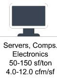
Cooling Load: The cooling load values will vary greatly on the amount of servers or electronics within the space. If you can get the equipment kW values or the number of racks then you can make a better estimate on the cooling load. You should only use the cooling load range in this calculator, if the equipment information is not known.
Shops, Shopping Centers:
Description: This building type includes convenience stores, supermarkets (excluding refrigeration load for freezers), drug stores, retail shops, barber shops, restaurants and cafeterias. These spaces have primarily people loads with slightly more than a sedentary activity level. High fenestration loads are also common and there is minimal equipment loads, except for television screens.
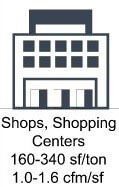
Cooling Load: The higher tonnage and airflow values are for buildings with unusually high amounts of fenestration and higher people density values than normal. For example, barber shops and boutique shops may have lower people loads and only one façade with fenestration, which would correspond to the lower cooling load values. Restaurants, cafeterias and large department stores that have higher people density values and multiple facades of fenestration will be at the higher cooling load values.
100% Outside Air (Labs, Hospital):
Description: 100% outside air spaces like laboratories and hospital spaces typically have fume hoods or large amounts of exhaust air that is required to remove contaminants from the space. This air must then be replaced with conditioned air. These buildings also have minimal fenestration and thus low external loads. There are minimal loads due to computers and other heat producing equipment.
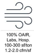
Cooling Load: Higher tonnage and airflow values in the range should directly correspond to building locations with hotter and more humid design conditions. Some labs may have industrial type equipment or other high heat producing equipment, which will cause the cooling load and airflow values to be on the higher side of the range. The lower end of the range is more applicable to buildings with only computers, copiers and other office type equipment.
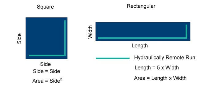
Section 4.1.3: Building Shape
The shape of the building determines the hydraulically remote run for both chilled water pump and air handling unit calculations. If you choose a square type building then the hydraulically remote length is two times the side of the building. If you choose a rectangular type building, then the hydraulically remote length is the length plus the width of the rectangle. The side for the square building and the length/width for the rectangular building are found with the equations below.
Section 4.1.4: Building Location
The options available on the drop down menu may not exactly match up to your specific building location. When this occurs you should find the nearest weather station data in ASHRAE Fundamentals or at the following link below. Then you need to find the 0.4% cooling dry bulb value and corresponding wet bulb valve and insert these values to override the location data. Next, you need to find the 1% heating dry bulb valve and insert this value.
The 0.4% and 1% values correspond to the number of hours that the location will have temperatures of these values or worse within the year. For example, the cooling load design outdoor conditions have a 0.4% design condition, which means that the design outdoor conditions will occur approximately 35 hours in a year.
0.4%*8,780 hours=35.04 hours
The inverse of these values can also be encountered in the HVAC field. For example, if you design your HVAC system for the 0.4% outdoor design condition then your system can meet the cooling load 99.6% of the hours within the year.
The next term that you should understand is the mean coincident value. This is the average of the coincident values during the outdoor design condition. For example, let’s say the 0.4% cooling dry bulb value is 99 °F. This value or higher occurs 0.4% of the hours throughout the year. However, when the dry bulb is greater than or equal to 99 °F, there is also a set of coincident values for wet bulb. The conditions may be as follows, 99 °F/87 °F, 99 °F/84 °F, 100 °F/89 °F, etc. The average of all the wet bulb values for the 35.04 hours is the mean coincident wet bulb.
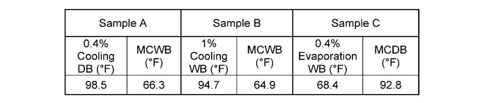
The previous table shows sample conditions to help reinforce the concept of mean coincident values. Sample A is the 0.4% cooling dry bulb of 98.5 °F and the mean coincident wet bulb of 66.3 °F. Sample B is the 1% cooling dry bulb and mean coincident wet bulb values. You would expect that these values would be lower, since they occur a larger percentage of the time and it does show that the values are lower. Sample C shows the 0.4% evaporation wet bulb. Only 0.4% of the hours of the year has a wet bulb condition of this value or greater. The coincident average dry bulb at this condition is shown as 92.8 °F.
Section 4.2: Choosing the Cooling System Type
There are four system types that you can select. A brief summary of each system is shown in the table below and then each system is covered in more detail following this section.
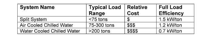
The previous table has a range of tons applicable for each system type. This table was created with a primary focus on return on investment. In the split system, the condenser and evaporator are both air cooled, which will cause low thermal efficiencies in heat transfer. This will increase electricity usage and operating costs. The air cooled chilled water system has its condenser air cooled but its evaporator is water cooled by the chilled water. This increases efficiency but also increases initial construction cost. The increase in initial construction cost will only reap sufficient electricity usage savings if the amount of cooling is high. Finally, the water cooled chilled water system has its condenser and evaporator both water cooled. The condenser is cooled with condenser water and the evaporator is cooled with chilled water. This increases full load efficiency to 0.6 kW/ton.
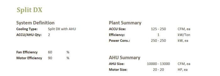
Section 4.2.1: Split System/Packaged A/C
Split systems consist of an outdoor air cooled condenser units and an indoor fan coil unit. In between the two units are two sets of refrigerant piping. The calculator will size the total tonnage required to cool the building and it will also divide the total tonnage equally between the number of air cooled condensers or fan coil units you will have in your system. For example, you could provide one fan coil unit for each room in a two-story walk-up apartment. However, you could have one large air cooled condensing unit for each floor, for a total of two air cooled condensing units.
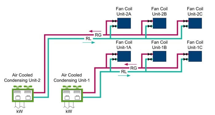
The refrigerant piping consists of a supply line which is refrigerant liquid (RL) and a return line which is hot refrigerant gas (RG). The refrigerant liquid (RL) enters the fan coil unit, where it is first expanded into a cold saturated liquid and then evaporated as the liquid is used to cool the air blown over the evaporator coils. The refrigerant gas (RG) is then sent back to the air cooled condensing unit, where the gas is compressed and then cooled and turned into a liquid via the condensing coils and fans. Finally, the refrigerant liquid (RL) is then sent back to the fan coil unit and the cycle repeats.
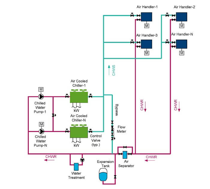
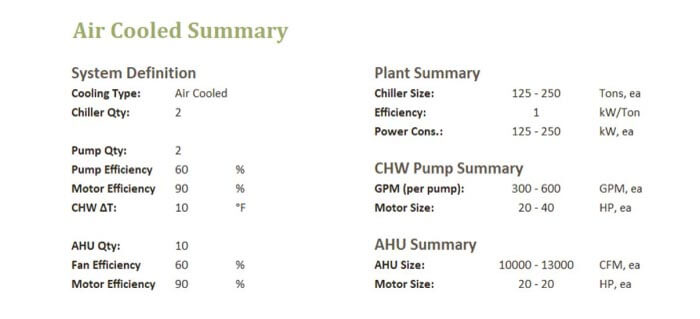
Section 4.2.2: Air Cooled Chilled Water System Type
An air cooled chilled water system consists of at least one air cooled chiller that uses outdoor air to provide heat rejection for the refrigeration cycle. This system includes air cooled chillers located outdoors, chilled water pumps which may or may not be located outdoors as well. Inside of the building are chilled water air-handling units (AHU) or fan coil units (FCU). These units typically consist of a chilled water coil, heating coil, filter and a fan/motor.
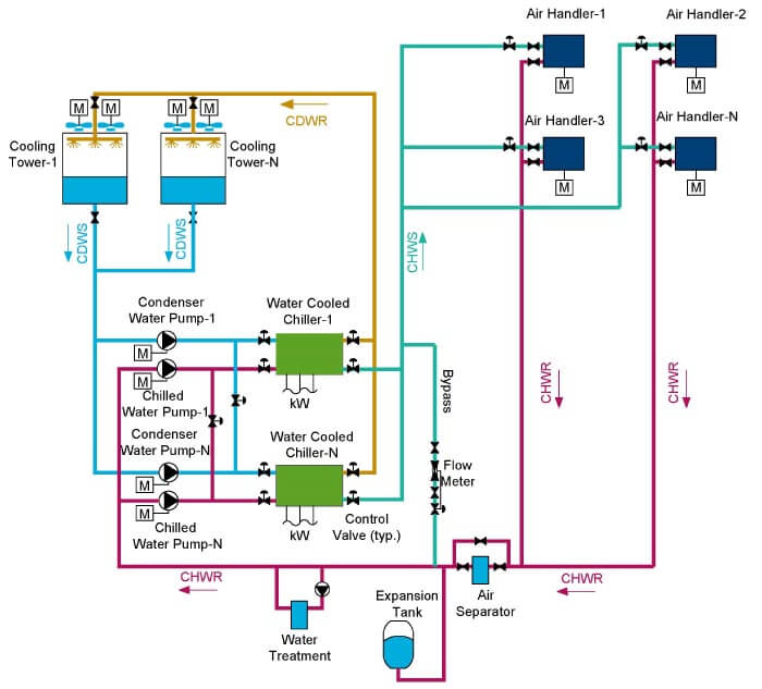
Section 4.2.3: Water Cooled Chilled Water System Type
A water cooled chilled water system consists of at least one water cooled chiller that uses condenser water to provide heat rejection for the refrigeration cycle. This system includes water cooled chillers, chilled water pumps, condenser water pumps and ancillary equipment like the water treatment system, expansion tank and air separator all located indoors. Additionally inside of the building are chilled water air-handling units (AHU) or fan coil units (FCU). These units typically consist of a chilled water coil, heating coil, filter and a fan/motor. Located outdoors are cooling tower(s) that use evaporative cooling to cool the condenser water.
Section 4.3: Choosing the Heating System Type
Section 5.0: Understanding the Outputs
The outputs of the calculator can be used to give a range of values for the total cooling load and equipment sizes which can then be used for space and budgetary planning. In order to better understand how the outputs are created, each output and the equations governing each output will be discussed.
Section 5.1: Cooling Load
The cooling load shows the total tons of cooling and airflow required for the entire building. These values are based on the building type, which determines the SF/ton value and the CFM/SF value and the total building area (SF).
You should use the building type discussion in Section 4.0 to give you a better idea of where your building is within the cooling load range. For certain building types the range can be quite large, so you will need to make a decision as to which end of the range your building fits or if the building is in the middle of the range.
Section 5.2: Heating Load
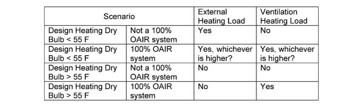
The heating load is only activated in the event of one of the following two scenarios: (1) Design Heating Dry Bulb Temperature less than 55 °F or (2) 100% OAIR System. If the design heating dry bulb temperature is below 55 °F, then the air is sufficiently dry and must be heated before it is sent into the building. If the design heating dry bulb temperature is above 55 °F, then the air must still be cooled down to 55 °F and then sent into the building. This is true for areas like Hawaii, where most buildings do not require heating because the outside air is never sufficient cold. However, heating may be required in 100% outside air systems because in these systems air can be 55 F or below and will need to be heated up to the design indoor heating temperature. Although air is not required for comfort cooling/heating, air is still provided to meet fresh air requirements. The calculator goes through the following four scenarios and calculates the heating load based on either the external heating load or ventilation heating load.
The heating load is broken up into two parts, the (1) heating required from the external conduction through the walls/windows & roof and (2) the heat required to increase the temperature of the ventilation air.
Heating External Load: The external heating load is based on the external surface area, the difference between the outdoor design heating dry bulb temperature and the indoor design heating dry bulb temperature. The default indoor design heating dry bulb temperature is 68 °F. The area is determined by your inputs for building height and building perimeter. Lastly, the equivalent U-value for the external façade, including fenestration is given as shown in the equations below.
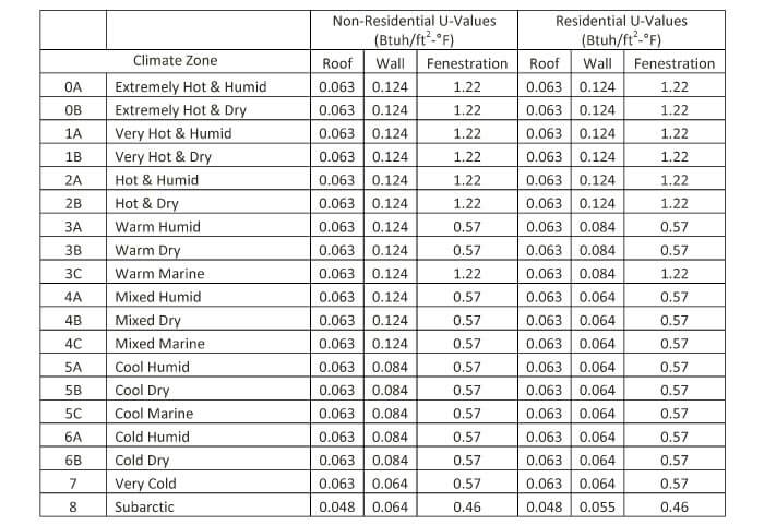
The climate zones are based on the tables in ASHRAE 90.1. The calculator automatically selects the correct zone for the location you choose in the drop down menu. However, if your location is not in the drop down menu or a similar location is not in the menu, then you will need to look up the climate zone in ASHRAE 90.1.
Heating Ventilation Load: The heating ventilation load is calculated differently, depending on which scenario your building falls under.
Scenario 1: Design Heating Dry Bulb less than 55 °F and 100% OAIR system. The airflow from the cooling load calculation is multiplied by the difference in temperature between the design heating outdoor dry bulb and the design heating indoor dry bulb.
Scenario 2: Design Heating Dry Bulb > 55 °F and 100% OAIR system. The airflow from the cooling load calculation is multiplied by the difference in temperature between the design heating outdoor dry bulb and the design cooling indoor dry bulb.
Section 5.3: Split System/Packaged A/C Unit Type
The split system/packaged unit selection shows the power and HVAC sizing for window air conditioners, split systems, packaged units and heat pumps. This calculator is meant for air cooled equipment, but you can also adjust the efficiency to match a water cooled heat pump.

Section 5.4: Air Cooled Chilled Water System Type
The air cooled chilled water system consists of air cooled chiller(s), chilled water pump(s), and air handling unit(s). The equations governing the other equipment will be explained in detail in this section.
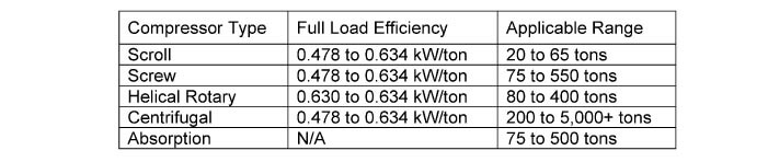
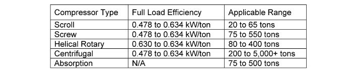
Chillers (CH): The major manufacturers of air cooled chillers include Trane, McQuay and Carrier. The efficiencies of the various air cooled chillers from these manufacturers range from 0.6 to 0.8 kW/ton. Each manufacturer may have their own variations and names of their air cooled chillers, but the thermodynamics will still be the same for each manufacturer. The only major differences in efficiencies can arise when the compressor type is changed. This table shows the typical efficiencies for various compressor types based on research into the product data of the air cooled chiller manufacturers.
Chilled Water Pumps (CHWP): The power value of the pump is found with the pump efficiency, GPM, FT. HEAD and motor efficiency. Each of these values will be discussed in this section.
In the calculator, the default pump efficiency is given as 75%. However, you can adjust the efficiency within the typical range between 65% and 85%. The pump efficiency is greatly dependent on the operating point of the pump and the manufacturer of the pump.
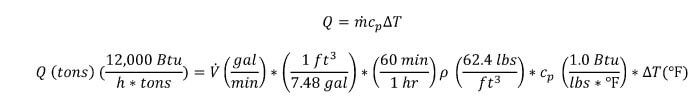
The flow rate (GPM) is found by taking the total tons and dividing this value by the heat capacity of water, the change in water temperature (typically 10 F) and conversion factors.
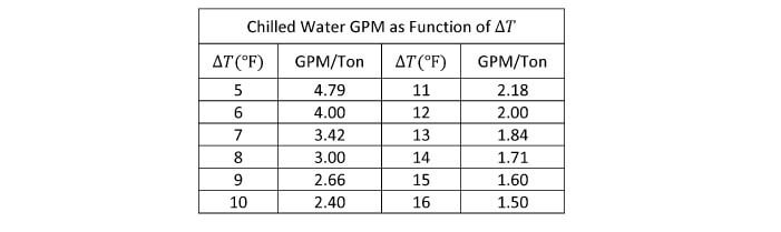
The above equation results in the following table. The difference between the chilled water supply and return will create a “delta T”. This term is used to determine the flow rate (GPM) required to satisfy the cooling load (tons). The most common “delta T” is 10 °F, which results in 2.4 GPM/Ton.
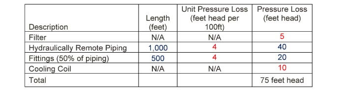
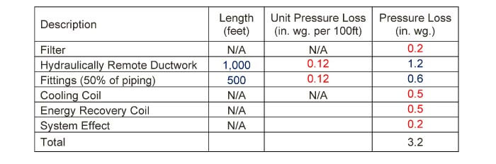
Once the flow rate (GPM) and efficiency values are found, the next calculation is finding the pressure loss in the piping system. Since, there is no piping system, you must make certain assumptions to quantify the piping system. This calculator takes the hydraulically remote length and applies a typical pressure loss per 100 feet factor. It also assigns an equivalent length for fittings. Typically fittings are given an equivalent length of 50% of the hydraulically remote length. The next major losses are the losses through the chilled water coil at the hydraulically remote air handler and the chiller. Typical values for these losses are also inserted in the table below.
Now, with all of the previously components, the calculator finds the brake horsepower requirements of the chilled water pump with the following equation.

Lastly, the pump needs a motor to provide the power to spin the pump. The motor will need to provide more than the pump power because there will be losses due to motor inefficiencies. Typically motor efficiencies range from 90% – 95%.

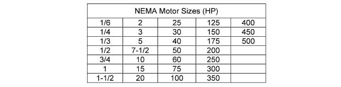
The calculator then uses the following table to find the smallest motor that can meet the horsepower (HP) requirements. Motors are built by manufacturers to match the frame sizes designated by NEMA Standards.
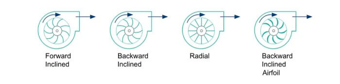
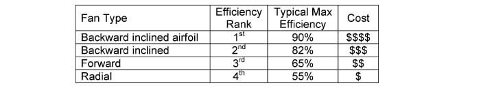
Air Handling Units (AHU): Air handling units can consist of a multitude of sections, but in its basic form an AHU consists of a fan section, coil section and filter section. The fan section will determine the fan type and thus the fan efficiency. The majority of the fan sections consist of a centrifugal fan with one of the following impeller types, (1) airfoil, (2) backward inclined and (3) forward inclined.
Section 5.5: Water Cooled Chilled Water System Type
The water cooled chilled water system consists of water cooled chiller(s), chilled water pump(s), condenser water pump(s), cooling tower(s) and air handling unit(s). The chilled water pump(s) and air handling unit(s) have the same equations as in the Air Cooled Chilled Water System Type. The equations governing the other equipment will be explained in detail in this section.
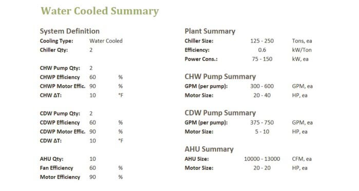
Water Cooled Chiller(s): The efficiency of the water cooled chiller is based on research of the products available from the following manufacturers: Trane, Carrier, York and Daikin. These manufacturers determined the lower limit of the efficiency values as shown in the table below. The higher limit of the full load efficiency values is based on ASHRAE 90.1 requirements. The default in the calculator is the higher limit of the full load efficiency values.
Absorption chillers are not included in this calculator. Absorption chillers typically use waste heat to drive the cooling and thus there will not be any electricity usage. Absorption chillers are rated based on their coefficient of performance (COP).
Chilled Water Pump(s): The chilled water pump calculations are the same as the calculations in the Air Cooled Chilled Water System section.
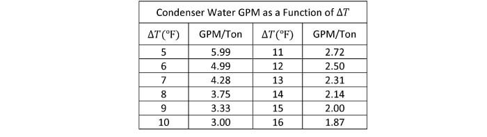
Condenser Water Pump(s): Condenser water pumps are similar to chilled water pumps, except the volumetric flow rate value is a function of 125% of the chiller tons and the difference in temperature between the condenser water supply and return temperatures.
The equation above results in the following GPM/ton values based on various “delta T” values.

Cooling Tower(s): The cooling tower size shown on manufacturers’ websites like Evapco, BAC, McQuay and Marley are shown in nominal tons. A nominal cooling tower ton is the amount of power to cool three GPM of condenser water from 95 °F to 85 °F. This is different from the tons used to quantify chillers. The definition of the nominal cooling tower ton results in the following relationship between cooling tower nominal tons and chiller tons.
The 125% difference between the cooling tower nominal ton and chiller ton is because a chiller is rated based on its useful cooling provided to the space. When the chiller provides this useful cooling, it removes the heat from the space but also adds in compressor heat that is typically 25% of the useful heat.

This makes it a little bit easier to select a cooling tower. If you have a 500 ton water cooled chiller, then you select a 500 nominal ton cooling tower.
The power using part of a cooling tower is the fan. The fan moves relatively dry air through the cooling tower and the air picks up moisture from the condenser water which causes the water to cool via evaporation. This is called evaporative cooling. The calculator compares the energy balance between (1) the condenser water side and (2) the air side. (1) The condenser water side equation is a function of the condenser water volumetric flow rate (GPM) and the difference between the condenser water return (CDWR) and condenser water supply (CDWS).

The air side equation is the airflow (CFM) multiplied by the difference in enthalpy between the entering air and exiting air. The enthalpy of the entering air is based on the design wet bulb temperature, since the enthalpy lines closely follow the wet bulb lines on a psychrometric chart. The enthalpy of the leaving air is similarly based on the leaving air wet bulb temperature.

The leaving air wet bulb temperature is found by keeping the same difference between the entering air wet bulb and leaving condenser water temperature as between the leaving air wet bulb and entering condenser water temperature.

For example, the CDWR is typically 85 °F and the CDWS is typically 95 °F. If the design air wet bulb temperature is 67 °F, then the leaving air wet bulb temperature will be 77 °F.
Air Handler(s): The air handler calculations are the same as the calculations in the Air Cooled Chilled Water System section.