- HOME
- FE EXAM
- PE EXAM
- DESIGN TOOLS
- COURSES
- STORE
- ABOUT
- CONSULTING
![]()
Engineering Pro Guides is your guide to passing the Mechanical & Electrical PE and FE Exams
Engineering Pro Guides provides mechanical and electrical PE and FE exam technical study guides, practice exams and much more. Contact Justin for more information.
Email: contact@engproguides.com
EXAM TOOLS
Power - Circuit Analysis
Circuit Analysis - 9 of 80 Problems
The section, Circuit Analysis, accounts for approximately 9 questions on the Power Engineering, Electrical PE exam. This section provides a refresher on the basic electrical engineering concepts, beginning with direct current. Following the direct current section, exam type material will be covered with alternating current, per-unit analysis and symmetrical components.
The circuit analysis section of this book will serve as the basis for many of the other application sections. Therefore, the terms explained here will be used in sections such as 4.0 Rotating Machines, 5.0 Electromagnetic Devices, and 6.0 Transmission. In the latter sections, it will be expected that that you have a strong understanding of the material presented in this section, 2.0 Circuits. Specifically, this section will introduce three methods of understanding circuits, (1) one line diagrams, (2) phasor diagrams and (3) waveforms. These three methods are the basic tools that will be used in the other sections previously mentioned. The symmetrical components and the three methods will also be used in 8.0 Protection.
The information shown on this website is a sample of the material provided in the technical study guide and sample exam. See the STORE to purchase these items.
Direct Current
The PE exam will most likely not have any easy direct current problems, so you may skip this section if you are already familiar with the basics of electricity. This section is only provided as a basis for the terms that are used in the other sections throughout this book.
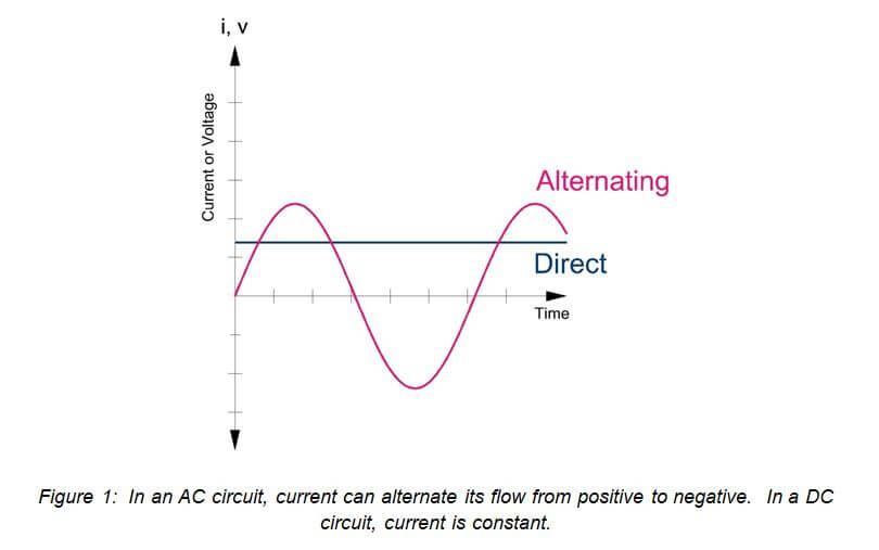
Direct current (DC) is the supply of current in one direction. In a circuit, current flows from the positive voltage terminal to the negative terminal. Current is deemed positive when it flows in this direction. Current is considered negative when it flows from a negative terminal to a positive terminal. DC current is a constant source and does not switch between negative and positive. Alternating current (AC) is able to supply current in both directions, positive to negative and negative to positive. This is shown in the graph below, where the current can be positive (above the 0-axis) or negative (below the 0-axis).
There are three main elements to a basic circuit, (1) current, (2) voltage and (3) resistance. The flow of electrons in a circuit is called current (I) and current is given in units of amperes. The energy that drives the flow of electrons is called the voltage (V) and is given in units of volts. The voltage is measured between two points because it is the difference in energy (also known as the potential) that drives the current from one point to the next. The third term is resistance, which is measured in units of ohms (Ω). Resistance (R) is the opposition to the flow of current. One ohm is described as the level of resistance that will allow 1 ampere to flow when 1 volt is applied to a circuit.
Ohm's Law
Ohm’s law describes the relationship between voltage, resistance and current. The voltage in a circuit is equal to the product of the current and the resistance in the circuit.

As voltage increases, in a constant resistance circuit, current will rise. As current increases, in a constant resistance circuit, voltage will rise.
Electrical Power
The next equation that you must know is the electrical power equation. This equation states that real power is equal to the product of the voltage and the current in a circuit. Real power is given in terms of watts.

If you combine Ohm’s law and the real power equation, then you will find two equations that show power as a function of resistance.

Kirchoff's Laws
There are two Kirchhoff’s laws that are necessary for the PE exam, (1) Voltage Law and (2) Current Law. The voltage law or KVL (Kirchhoff’s Voltage Law) states that the sum of voltages around a circuit loop is equal to zero. The current law or KCL (Kirchhoff’s Current Law) states that the sum of the current into and out of a node is equal to zero.
Kirchhoff’s Voltage Law (KVL)
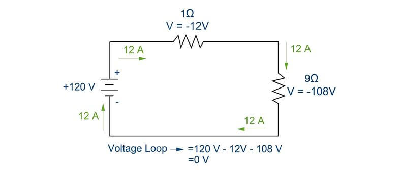
KVL describes the principle that in a circuit loop all voltage produced must be used by the devices in the circuit. There cannot be a change in voltage in a circuit loop.
KVL is also applicable when there is more than one voltage source in a circuit. Notice that the positive and negative terminals of the voltage sources are oriented in the same way, such that both voltage sources contribute positive voltage to the circuit.
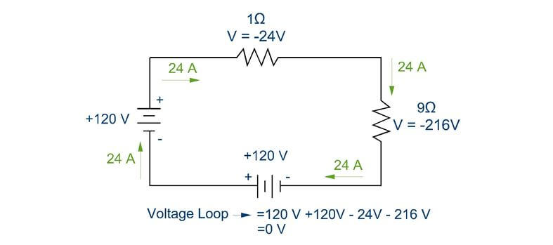
If the terminals of the two voltage sources were situated opposite from one another, then one voltage source would contribute positive voltage and the other would contribute negative voltage. The voltage source that contributed negative voltage would be similar to charging a battery and the positive voltage contribution would be a discharging battery.
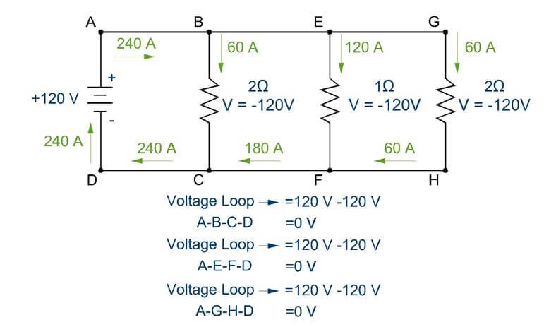
KVL also applies to circuits with multiple loops. Each loop must have its voltage sum equal to zero.
See technical study guide for continuation on Kirchhoff’s Current Law (KCL).
Circuit Arrangements
A complex circuit is made up of multiple devices and wires arranged in either series or parallel. These arrangements define the flow of current and the change in voltage with the following principles.
Series Circuits
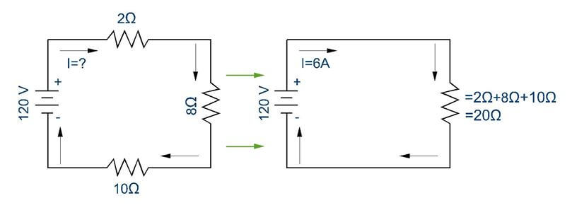
In a series circuit, the resistances are added to determine the equivalent resistance. Once you have a single equivalent resistance value, then you can determine the current flow through the circuit. The main concepts to understand are as follows:
(1) Current is constant through a series circuit and (2) resistances are summed to determine equivalent resistance.

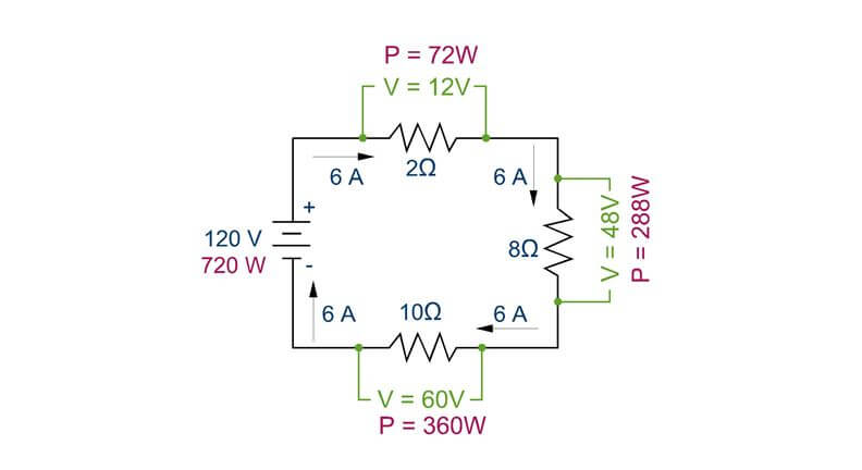
• Voltage Drop: In the previous figure, the voltage drop is found through each resistor by taking the current flow and multiplying it by the resistance. As you can see the voltage drops add up to 120V in accordance with KVL and the voltage drop magnitude varies directly with the resistance level in accordance with Ohm’s law.
• Power Consumption: In the previous figure, the power consumption is found through each resistor by taking the current flow and multiplying it by the voltage drop.
See technical study guide for continuation on parallel circuits , open circuits and short circuits.
Alternating Current
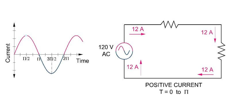
Alternating current is most commonly used on the PE exam and in most power applications. Alternating current describes the alternating directions of flow in a circuit. Current quickly alternates flow direction from positive to negative many times a second. In the figure below, positive current is shown flowing in a clockwise direction in the figure on the right and this flow direction corresponds to the positive portions of the graph on the left.
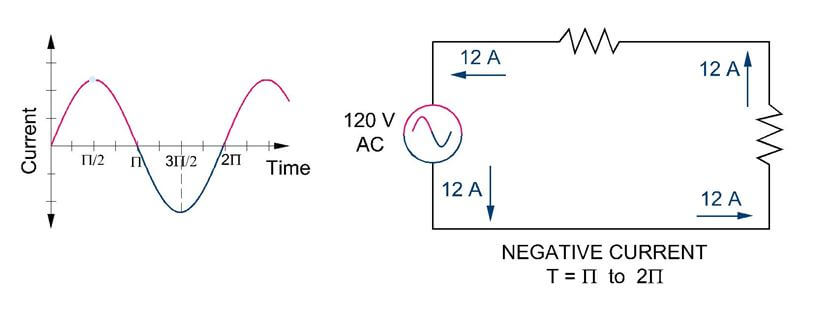
In this second figure, negative current is shown flowing in a counter-clockwise direction. The current flow in the figure on the right corresponds to the negative portions of the graph on the left.
Frequency
The frequency of an alternating current wave is the number of cycles completed in one second and is given in terms of hertz. For example, in the USA, the standard frequency for alternating current is 60 hertz (HZ). This means that 60 cycles are completed in one second. In Europe, the standard is 50 hertz (HZ). In the previous figures, 1 second would correspond to the 2π value, where the one cycle is completed.

Another term that is closely related to frequency is angular frequency. Angular frequency is the rotational frequency of alternating current and is given in terms of radians per second. For example, if one rotation is completed in one second, then the angular frequency is 2π. Angular frequency is related to physical frequency through the following equation.

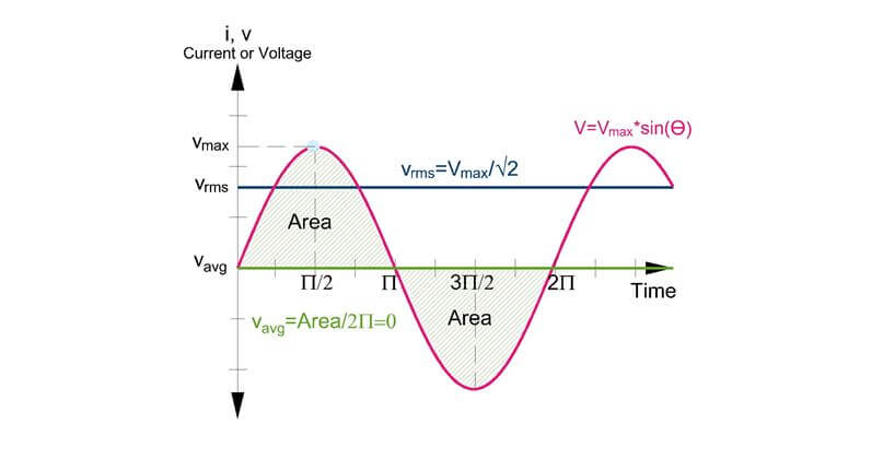
RMS and MAX
In an AC circuit, the voltage and current are constantly varying in magnitude over time. The RMS method is used to find the average or effective value of a constantly varying value. You may want to simply calculate the average of the value over time to get the effective value of the current or voltage, but in a simple AC circuit, the average will be zero because there are both positive and negative values. The term root mean square is found by taking the sum of “n” number of points along the waveform, squaring each value, summing all “n” values and then taking the square root of the sum.
See technical study guide for continuation on a lot of necessary circuit analysis topics. The list of the topics is shown below.
- RMS Equations for Various Waveforms
- Complex Numbers
- Converting between Polar and Rectangular
- Resistance, Inductance, Capacitance and Impedance
- Single Phase vs. Three Phase
- Delta vs. Wye Arrangements
- Converting between Delta and Wye
- Power Factor in Waveform and Equations
- Phasors - Leading vs Lagging
- Apparent Power, Real Power and Reactive Power
Symmetrical Components
The technique, Symmetrical components, is used to analyze unbalanced 3-phase loads (does not apply to 1-phase loads). This technique takes unbalanced loads and deconstructs the loads into three sets of symmetrical components, called the positive, negative and zero components. First, you should understand the difference between balanced and unbalanced loads.
Balanced vs. Unbalanced Loads
In balanced loads, each phase carries an equal amount of current that are each 120 degrees out of phase with one another. In addition, each of the phases has the same impedance and same voltage drop.

When each of the three phases reaches the load, the three phases “cancel” each other out, such that there is no return current.

Converting the polar form to rectangular form, you can see that the currents will sum to zero.

In a delta, 3 phase circuit, the phases must be balanced, due to KCL. However, if there is a wye, 4-phase circuit, then the KCL equation shall be as follows. The sum of the 3 phases and the neutral current shall be equal to zero.

In balanced loads, you know that the three phases add to 0, thus in a balanced load, the neutral will have 0 current and in an unbalanced load, the neutral will have a non-zero current.

However, you will need to use the symmetrical components technique if one of the following situations is presented in a question.
(1) The load is unbalanced. (2) There is a reference to positive, negative, zero components. (3) There is an unsymmetrical fault, which is presented in Section 6.0 Transmission under fault analysis.
Positive, Negative and Zero Components
The premise of the symmetrical components technique is that any unbalanced load can be expressed as a set of three balanced components called, (1) Positive sequence, (2) Negative-sequence and (3) Zero-sequence. The following figure shows an unbalanced load that has different magnitude phasors and phasors that are not 120 degrees apart.
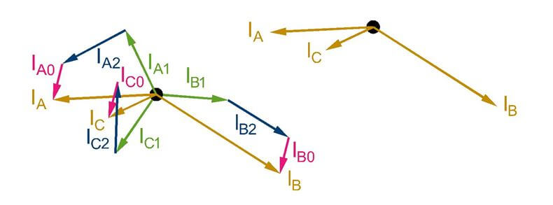
The figure above reconstructs the unbalanced load with three sets of symmetrical components. The individual sets of components can be seen below for clarity.
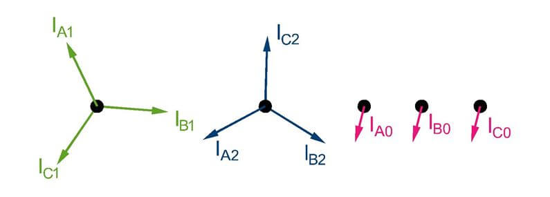
See technical study guide for discussion on symmetrical components, especially the equations for the components and how to convert between the components to the imbalanced phasors.
Per Unit Analysis
In complex circuits, with more than one voltage level, many of the previous equations are difficult to use. Thus, the per-unit method was created to convert currents and impedances to one common base voltage and/or power. The per-unit method creates base values (voltage, power, impedance and current) and all other values are described as a ratio to the base values. The base values are chosen by the electrical engineer.
• Step 1: Choose base power and voltage

When you select your base, remember that the base power is common for the entire circuit. The base voltage is typically selected for various zones. For example, the high side of a transformer will be one zone and the low side of the transformer will be another zone. Each of these two zones will have the same base power, but will have different base voltages.
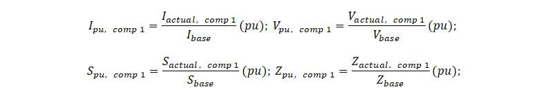
• Step 2: Solve for other base values. The below equations assume a single phase circuit or a 3 phase circuit that uses the phase voltage and the kVA per phase values. e

It is important to be aware of your selections in your base calculations, when you have a 3-phase system. For example, if you selected the 3-phase kVA and the base voltage as the line voltage, then your equation for solving the current will include the √3 term.

• Step 3: With the base values, find the per-unit vales for all components of the diagram
See technical study guide for more on Changing Per Unit Base and Examples.