- HOME
- FE EXAM
- PE EXAM
- DESIGN TOOLS
- COURSES
- STORE
- ABOUT
- CONSULTING
![]()
Engineering Pro Guides is your guide to passing the Mechanical & Electrical PE and FE Exams
Engineering Pro Guides provides mechanical and electrical PE and FE exam technical study guides, practice exams and much more. Contact Justin for more information.
Email: contact@engproguides.com
EXAM TOOLS
Protection
for the Power P.E. Exam
by Justin Kauwale, P.E.
Introduction
The section, Protection accounts for approximately 8 questions on the Power Electrical PE exam.
A protection system in power systems are designed to monitor the power system through voltage, current, phase, power factor and many other measurement devices. These devices are discussed further in the next section, Measurement and Instrumentation. This section, Protection, focuses on the protective devices that receive the signals from the measurement devices. These protective devices ensure safe and nearly continuous operation of the electrical power supply.
The topic of Protection is vast and some engineers may spend their entire careers as a Protection Engineer for a utility and may never learn all the intricacies of various protection schemes. However, the exam will not test this level of detail and should only cover the main concepts and skills in the topic of Protection. These topics include basic knowledge of the protective devices available, overcurrent protection calculations, protective relaying devices, relay and device coordination and the most common protection schemes for busbars, transformers, transmission lines, motors and generators.
The information shown on this website is a sample of the material provided in the technical study guide and sample exam. See the STORE to purchase these items.
Protective (Tripping) Devices
The first part of Protection that you should understand is the main types of tripping devices. These devices isolate faults from damaging equipment and injuring personnel. Faults and the different types of faults were previously discussed in the Transmission section. Tripping devices are part of an overall protection scheme. This protection scheme consists of, (1) Measurement device, (2) relay devices and (3) tripping devices. First, the measurement device, which is typically a current or potential transformer, will measure a value that is not within normal operating range and is unsafe during a fault condition. This value will cause the relay device which will send a signal to the tripping device to trip and disengage the circuit to isolate the fault. Tripping devices and relay devices are discussed in this section, but the measurement devices are discussed in the Measurement & Instrumentation section.
FUSES
The first type of tripping device is called a fuse. A fuse is one of the simplest tripping devices and actually encompasses all three parts of protection. A fuse consists of a metal element that heats up in direct relation to the current flow through the fuse. If the current is too high, the metal will get hot and melt the device and thus break the circuit. A fuse is selected based on the normal flow of current, the speed at which the fuse melts and the maximum amount of current at which the fuse will melt.
Fuses do not require a separate measurement device nor do fuses require a separate relay device, since the current is in a way measured mechanically by the melting of the fuse and there is no need to relay this information to the tripping device since the fuse is the tripping device as well.
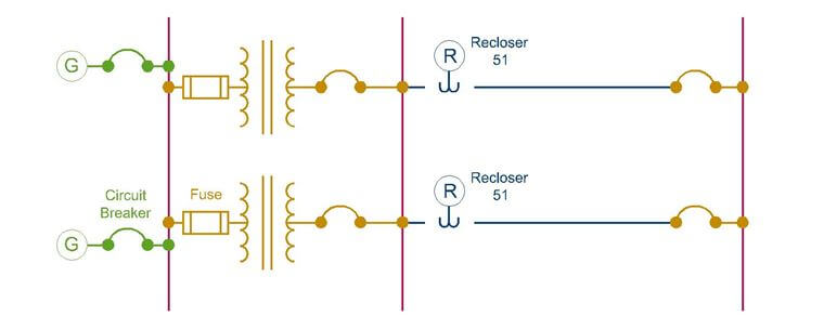
CIRCUIT BREAKERS
A circuit breaker is an electrical switch that interrupts the normal flow of current, based on an external signal. A breaker is in its simplest form a switch, it can be turned on and off. When it is turned on the circuit is complete and current flows from source to load and vice versa. When the circuit breaker is turned off, the circuit is broken and there is no flow of current from source to load and vice versa.
Unlike a fuse, a circuit breaker can be operated multiple times, like a switch. However, this type of switch has some additional features that make it more robust than a simple switch. Circuit breakers are rated by the amount of current that normally operates through the breaker when it is operating with normal current. But a circuit breaker must also be able to interrupt large amounts of current. This value is called the maximum short circuit current or the ampere interrupting capacity or maximum interrupting current. When the current is interrupted, an arc will form and the circuit breaker must be able to contain this arc. Arcs will be discussed more in the Codes and Standards section.
RE-CLOSERS
A re-closer is a type of circuit breaker that can automatically close the circuit, after the circuit breaker has opened the circuit due to a fault. This type of circuit breaker is used on transmission lines and not used in distribution systems. Re-closers are used on transmission lines, especially overhead transmission lines, because the faults in a transmission line are normally cleared by itself, meaning that the faults are transient. Some power companies estimate that 80-90% of faults are transient. This means that the majority of faults may occur for a second, but then return back to normal. In order to avoid unnecessary outages to transmission lines, re-closers are installed in lieu of normal circuit breakers on transmission lines. Re-closers also have additional capabilities to account for the other 10-20% of faults that are permanent faults. If a fault is permanent, then the re-closer had multiple attempts at different time intervals to close the circuit. If the circuit does not close after the last attempt, then the re-closer will remain open and require personnel to clear the fault. The time between attempts and the number of attempts can all be programmed into the re-closer.
Overcurrent Protection
In order to protect electrical equipment and to limit the damage of short circuit current, overcurrent protection devices (OCPD) are installed to break the circuit and stop the flow of the current. As an electrical engineer in the power field, you will most likely be required to size an OCPD and these devices must be sized to meet (1) the rated current, (2) the rated voltage and (3) the interrupting current.
- (1) Voltage Rating: The voltage rating is the rated voltage at the location of the overcurrent protection device. If a bus is operating at 240 V then the OCPD must be at least equal to or greater than 240 V.
- (2) Current Rating: The current rating must be less than the rating of the conductor that connects the OCPD. However, conductors are usually rated for very high amperes when compared to the OCPD. In order to get the current rating of the OCPD you should check the NEC section. An OCPD usually has a current rating of 125% the continuous load current on the conductor.
- (3) Interrupting Current or Short Circuit Current: The short circuit current value shall be discussed in the next section and this value should not be confused with (2) Current Rating.
SHORT CIRCUIT CURRENT
Short circuits occur when electricity flows on a path of very little to no resistance. In a circuit, a short occurs when a new path is made that bypasses the load (resistance), this reduces the circuit’s total resistance to a very small value. When the resistance is very small, the current will be very high, which will increase the heat load within the circuit and will create a dangerous environment.
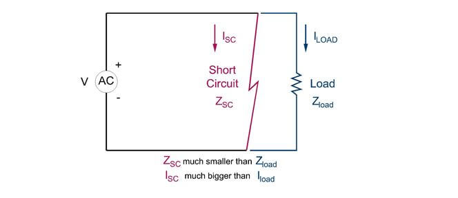
In a short circuit, the normal load is bypassed and replaced with little to no resistance.
Short circuit MVA flows are found for all components in a power system through the next following equations. These values assume the component is supplied with power and the component is short circuited at its terminals.
Transformer Fault
In the transformer section, you learned that the percent impedance value is found by short circuiting the secondary and raising the voltage until you have full load current on the secondary. Thus when you raise the voltage to full load voltage and there is a short circuit, then the multiplication of the ratio of 100% to the percent impedance by the full load current will equal the short circuit current. It is important to note that this short circuit current is for a 3-phase fault.

For the MVA method, which is discussed later, you will need the short circuit MVA. This value describes the total amount of apparent power through a transformer during a 3-phase fault. This value is found similarly to the short circuit current value.

Generator/Motor Fault
Generators and motors are tested by manufacturers and are given various ratings. One important rating in a short circuit calculation is the sub-transient reactance. The sub-transient reactance assumes that the resistance component of the equivalent circuit of a generator/motor is ignored and only the inductance is used, hence the term reactance.

For the MVA method, similar to the transformer, you will need the short circuit MVA for the MVA method. This value describes the total amount of apparent power through a transformer during a 3-phase fault. This value is found similarly to the short circuit current value.

The information shown on this website is a sample of the material provided in the technical study guide and sample exam. See the STORE to buy the products for continuation on Protection including the following topics:
- Calculating Transmission Line Fault Values
- MVA Method and Examples
- Per Unit Method and Examples
- Protective Relaying
- Overcurrent/Undercurrent Relays
- Overvoltage/Under-voltage relays
- Directional Relays
- Differential Relays
- Distance Relays
- Coordination
- Primary and Backup Relaying
- Time Current Coordination Graphs