![]()
Engineering Pro Guides is your guide to passing the Mechanical & Electrical PE and FE Exams
Engineering Pro Guides provides mechanical and electrical PE and FE exam technical study guides, practice exams and much more. Contact Justin for more information.
Email: contact@engproguides.com
EXAM TOOLS
Power System Performance
for the Power P.E. Exam
Introduction
The section, Power System Performance, accounts for approximately 6 questions on the Power Engineering, Electrical PE exam.
Power system performance includes topics like power flow, load sharing and stability. These topics are vaguer than the other sections. These topics also involve computer software to complete many of the problems encountered in the actual practice in this field of power engineering. There are some basic concepts that govern these problems that might be tested on the exam, but this guide focuses on the concepts that have a higher probability of being tested.
Also notice that there are only 6 questions on this section, according to the NCEES exam outline. There is less opportunity for the test creator to ask detailed questions because they need to ensure that you have the minimal capability in this vast area of focus within only 6 questions and each question can only take 6 minutes to solve.
The information shown on this website is a sample of the material provided in the technical study guide and sample exam. See the STORE to purchase these items.
Power Flow
In power engineering, power flow is the analysis of the power throughout a system. This analysis tracks voltage magnitude, voltage angle, reactive power and real power throughout the power system. If you can track these items through the equivalent circuits discussed in rotating machines and transformers, then you understand the basics of power flow analysis.
Power flow analysis also tracks the same items in the equivalent circuits for various scenarios like short circuit, fault analysis, harmonic analysis and motor starting. The analysis can get very long and even require iterations, since there will be multiple unknown variables in the system. Therefore, this analysis is always completed through the use of software like Paladin Design Based, which is linked below.
Manufacturer's Link: Paladin Design Base
For the purposes of the exam, power flow analysis is too specific and difficult to test with a 6 minute problem. Thus you should only know the basics of power flow analysis. If you want real life context on power flow and a look at how power flow analysis is conducted in practice, then I suggest you read through these case studies and tutorials from the actual power flow analysis software.
Manufacturer's Link: Basic Power Flow Tutorials
Manufacturer's Link: Power Flow Case Study
Manufacturer's Link: Advanced Power Flow Guide:
Power Flow Basics
When setting up a circuit for power flow analysis on a computer software program you must create buses. Power flow software has a limit on the amount of buses that can be created before the computations become too taxing even for a computer. There are three types of buses used in a power flow analysis: load bus, voltage-controlled bus, and a slack bus. A voltage controlled bus is defined as a bus that maintains a constant voltage to the system, which is accomplished with a generator. A load bus is anything that isn’t a voltage controlled bus. The slack bus has a varying voltage that is used to balance the difference between the voltage controlled buses and the load buses.
In between the buses are the passive elements, like transformers, transmission lines, reactors and capacitors. These elements react to the circuit, but cannot manually affect the circuit. Transformers are modeled with their apparent power, voltage and their impedance. Transmission lines are modeled with their impedance, length and wire size. More detailed transmission lines can also be modeled as short, medium or long in accordance with the Transmission and Distribution section.
Active elements like motors, generators and loads are characterized as elements that can be adjusted to affect the circuit. These elements have parameters that may vary as a function of time. Each of these active elements can be modeled with any two of the following four elements (apparent power, real power, reactive power and power factor). When all elements are connected to a bus, you are also determining the elements’ voltage. In addition, the active elements can either be classified as a constant power, constant impedance of constant current element. These terms determine how the element will react when there is a variation in the voltage supplied to the element. Because the circuit will not be able to provide the exact voltage required to each element and thus the element must vary the power, current or impedance based on the varying voltage. However, you as the power system modeler can choose which one of those characteristics cannot be varied.
Once you have set up your model and connected all the items, the software will complete through many iterations, in order to find the best solution that determines the following at each bus and each load.
- Buses: All voltages and relative phase angles.
- Passive Elements: Power, current, % capacity used, voltages, phase angles
- Active Elements: Power, voltage, current, phase angles
The results of this power flow analysis will determine if certain conditions will cause equipment to be overloaded or if there will be poor voltage levels at buses.
Once your model is complete, you can also complete other studies that were previously mentioned but are also listed below for completion.
- Short Circuit Analysis
- Motor Starting Analysis
- Harmonic Analysis
- Reliability/ Voltage Sag Analysis
- Cable Ampacity Analysis
- Protective Device Coordination Analysis: This requires you to also add all protective devices into the circuit.
Load Sharing
Load sharing is the study of how load is distributed through parallel equipment like generators and transformers. On the PE exam, you may be asked to calculate the load shared between generators and transformers of various characteristics. This section will go through each of the different scenarios, to help you to understand how the equipment characteristics affect the load flow and to save you time when completing problems on the exam.
Parallel Generators
Total power from generators operating in parallel is equal to the sum of the powers of each individual generator.

The power provided by parallel generators is equal to the sum of each generator’s individual power.

There are four major criteria for generators in parallel: (1) the frequency set point of the generators be equal the load frequency, (2) the voltage is provided at the load voltage requirement, and (3) the total real and reactive power produced is equal to the load and (4) the voltages are in phase and in sequence. To accomplish this, the speed governor and the field current are adjusted for one or both generators until the load power requirements are met.
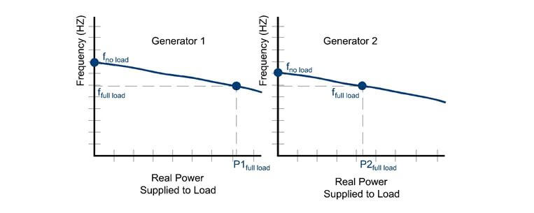
The frequency of the generators affects the real power delivered by each generator.
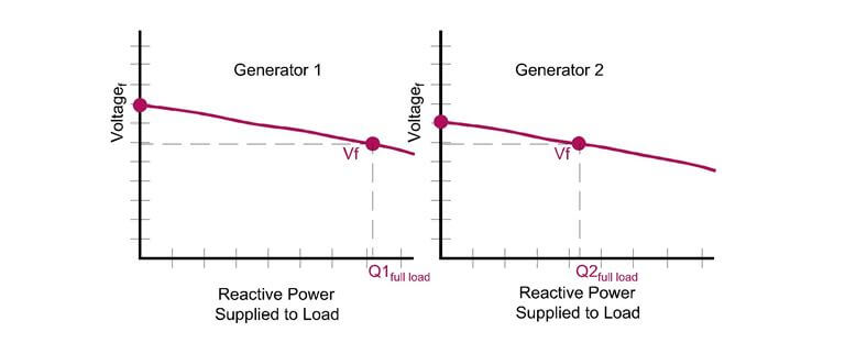
The voltage created by the field current affects the reactive power provided by each generator.
In practice one generator will be serving the load and then a second generator must be turned on to accommodate the additional load. The second generator’s speed governor is adjusted so that the generator frequency is close to the first generator’s frequency. Then the excitation is adjusted so that the voltages are equal. Finally, the second generator must be connected only when the second generator is in phase with the first generator. Once the generators are in phase, then the circuits are quickly connected and the generators will be in parallel with each other.
Droop Compensation
Once the generators are connected in parallel, then they must work together so that the frequency and voltages are the same, in response to an increase or decrease in load. The simplest way to make sure the generator is to use droop compensation. Voltage droop is the designed loss of output voltage as load increases. A circuit is added to the output of each generator and as the load changes, the control circuit will adjust the frequency and excitation of both generators’ in the same manner.

Infinite Bus
In most situations, the generator will be connected in parallel with a large power grid. A large power grid is represented as an infinite bus, where the power grid is so large that the generator will not affect the characteristics of the system. An infinite bus is therefore said to have constant frequency and voltage. Thus you do not need droop compensation. When a generator is paralleled with an infinite bus, it must match the voltage and frequency of the infinite bus. Right before connection to the grid, the frequency of the generator must be slightly higher, as to be sure that power will not be absorbed into the generator.
Recall the discussion of field current and speed control in the Generator Control section of Chapter 4 – Rotating Machines. Review the equivalent circuits and the derivations of the vector diagrams for better understanding of the discussion below.
Real Power: Real power is controlled by the frequency of the generator shaft. In an infinite bus system, the generator frequency must match the power grid frequency. Therefore, to increase the real power supplied from the generator, fuel is added to accelerate the rotation of the rotor until the internal voltage is out of phase from the terminal voltage by an angle δ, known as the torque angle. The larger the torque angle, the larger the power to the power grid. Once the phase shift is set, the generator resumes operating at normal frequency. The real current of the current produced will generate real power to the grid.
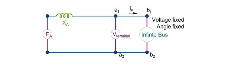
In an infinite bus connection, the terminal voltage is locked by the infinite bus voltage.
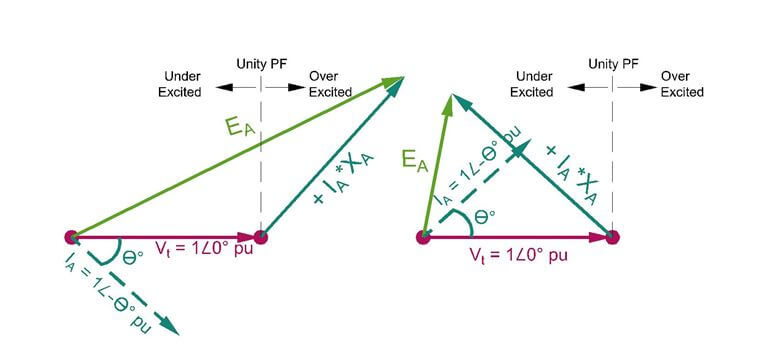
The voltage angle and magnitude of the generator voltage adjusts based on the current phase angle aka power factor. If the power factor is lagging, then the generator voltage will be larger than the terminal voltage, as shown in the figure on the left. If the power factor is leading then the generator voltage will be under-excited as shown in the figure on the right.
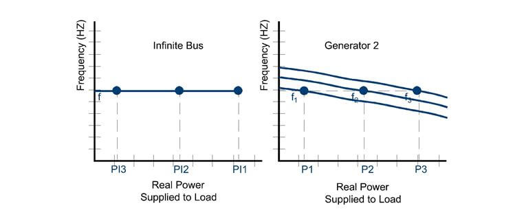
The infinite bus locks the frequency of the generator output. The only way to change the real power output is to shift the generator curve up and down.

The same concept is true for the reactive power supplied to the load. The voltage terminal is locked by the infinite bus, thus the reactive power curve must be shifted up and down to change the amount of reactive power supplied to the load by the generator.
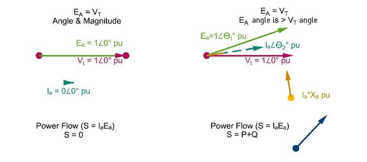
The generator voltage and the infinite bus voltage are in phase and of equal magnitude in the original condition. This results in no current transfer and no power flow between the generator and infinite bus. In the right condition, the phase angle of the generator voltage is increased. This creates positive power flow, meaning power flows from the infinite bus to the generator.
Reactive Power: Reactive power is controlled by the excitation current, also known as the field current. By increasing the field current, the armature current increases. The armature current flows through reactive impedance, XA, which causes the current to lag the internal voltage by 90 degrees, where it falls on the reactive axis.
+Q, Reactive Power Supplied to Grid: When the internal voltage of the generator, EA, is larger than the terminal voltage, ET, the voltage potential difference, Ed=IAXA, across the reactor will be positive, causing reactive power to be supplied to the grid.
The same original condition is provided on the left. Then the generator magnitude is increased to be larger than the terminal voltage. This creates in a negative reactive power, meaning reactive power flows from the generator to the infinite bus.
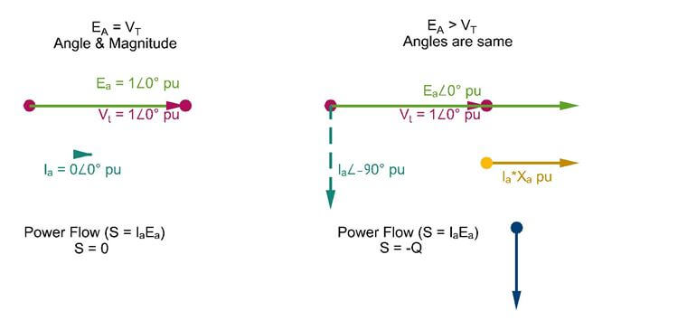
-Q, Reactive Power Absorbed from the Grid: When the internal voltage of the generator, EA, is less than the terminal voltage, ET, the voltage potential difference, Ed=IAXA, across the reactor will be negative, causing reactive power to be absorbed from the grid.
The same original condition is on the left. Then the generator voltage magnitude is decreased less than the voltage terminal. This creates a positive reactive power, which means reactive power flows to the generator from the infinite bus.
The information shown on this website is a sample of the material provided in the technical study guide and sample exam. See the STORE to buy the products for continuation on Distribution Analysis including the following topics:
- Parallel Transformers
- Paralleling Different KVA Transformers
- Paralleling Different Impedance Transformers
- Paralleling Different KVA and Different Impedance Transformers
- Paralleling Different X/R Ratio Transformers
- Paralleling Different Tap Settings, Voltage Ratio, Turns Ratio Transformers