- HOME
- FE EXAM
- PE EXAM
- DESIGN TOOLS
- COURSES
- STORE
- ABOUT
- CONSULTING
![]()
Engineering Pro Guides is your guide to passing the Mechanical & Electrical PE and FE Exams
Engineering Pro Guides provides mechanical and electrical PE and FE exam technical study guides, practice exams and much more. Contact Justin for more information.
Email: contact@engproguides.com
POWER PE TOPICS
Codes and Standards
Power - Codes & Standards
Codes & Standards - 10 of 80 Problems
The section, Codes & Standards, accounts for approximately 10 questions on the Power Engineering, Electrical PE exam. The codes and standards section of the exam is the section where most people do well on the exam. Many of these questions on the exam, simply test your familiarity with the NEC and NESC. You should be well prepared to go to any section in the book, although some sections of the codes are more used than others. The most common questions are highlighted in this section of the book. Also included in this section is a technique that you can use to quickly navigate to the correct part of the code to answer a question on the exam. This technique involves memorizing the format of the book, such that if you are given a certain type of code question, you will know exactly what section to look into in the book.
The information shown on this website is a sample of the material provided in the technical study guide and sample exam. See the STORE to purchase these items.
National Electric Code (NEC)
The National Electric Code or NEC is the governing code for the installation of electrical equipment, wiring and related materials from the service point to the user loads.
The NEC does not apply from the service point to the utility. The National Electrical Safety Code or NESC is the governing code from the utility to the service point. The service point is typically the point of connection to a utility system. The user loads could include an industrial motor, a residential receptacle, a parking lot light and many other types of loads.
However, the NEC does not apply in specialty areas like ships, aircrafts, vehicles and mobile homes. For example, the NEC would apply to the wires and outlets of an electric vehicle charging station but it would not apply to the inner electrical system of the electric vehicle. The NEC also does not apply to other specialty areas like mines, railways, communications utilities and electric utilities.
The NEC does apply to more typical applications like residential, industrial, commercial, educational, institutional, retail, assembly, factory, storage and other building type applications.
The purpose of the NEC is to provide the minimum requirements to promote a safe installation. Design electrical engineers must ensure that their designs meet these requirements at a minimum. The NEC does not tell electrical engineers how to design.
The following is an outline of the code. The following sections will go provide an overview of each chapter and the important sections that may be on the exam.
- Chapter 1: General
- Chapter 2: Wiring and Protection
- Chapter 3: Wiring Methods & Materials
- Chapter 4: Equipment for General Use
- Chapter 5: Special Occupancies
- Chapter 6: Special Equipment
- Chapter 7: Special Conditions
- Chapter 8: Communication Systems
- Chapter 9: Tables
If you do not already have the NEC 2014, then you should purchase your own copy.
Amazon Link for Purchase: NEC 2014
Color Coded EZ Tabs for the 2014 National Electric Code
These sets of tabs help to organize the NEC into the code’s various sections. The tabs are sturdy and are also color coded to help you quickly navigate the NEC during the exam. The NEC questions require you to look-up important tables and excerpts. These questions will be much simpler than the other questions on the exam and you should do these questions quickly. If you are able to complete these questions quickly, then you will have more time to complete the more complex problems on the exam. These tabs will help you to complete these problems quickly, but you should also not rely solely on these tabs and you should also tab the important tables and excerpts that are highlighted in the following sections.
Amazon Link for Purchase: Color Coded EZ Tabs
Key Word Index
This book is an additional index to the NEC. The breakdown of key words simplifies and speeds up the referencing process, saving you valuable time on the test and helping you to better navigate through the code book. The Key Word Index is available for specific years of the NEC.
Amazon Link for Purchase: Key Word Index
Chapter 1: General
The general installation requirements include warning labels, clearances, material standards, etc. However, the general requirements chapter is difficult to test, when compared to the following chapters which include calculations and specific answers without exceptions. One part of the general requirements chapter that is used in practice regularly is the equipment clearance section. Electrical engineers that work in the building power design field use the clearance requirements in coordination with other engineering disciplines and architects to ensure that there is a safe clearance around the equipment.

Chapter 2: Wiring and Protection
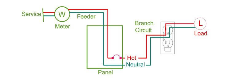
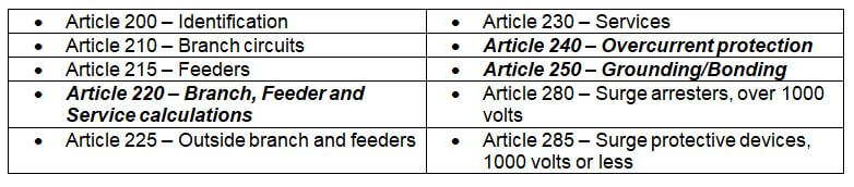
This section covers the identification, installation, sizing and over protection for branch circuits, feeders and services. Branch circuits are the circuits from panels that feed outlets, appliances and loads. Feeders are the conductors that feed the panels, transformers and buses. The service is the conductor(s) from the utility onto the premises. The following is an outline of the articles in Chapter 2, Wiring and Protection.
The following sections are the most important things to understand for the PE exam, because these sections are most commonly used in practice and are testable within six minutes.
Article 220 Load Calculations
Article 220 includes the minimum requirements to calculate the loads on branch, feeder and service conductors.
Branch Load Calculations: The apparent loads on a circuit help you to determine the current, which will help you to size the conductors. However, the amount of load on an outlet or in a lighting circuit can be subjective, because the designer is not always aware of the loads that will be plugged into a receptacle, nor are they aware of how the loads will be operated. The NEC and specifically this article set a standard minimum load for many types of loads like receptacles. For example, in this section you find the minimum load on a duplex receptacle is 180 VA and the minimum load on a quadplex receptacle is 360 VA. Article 220 also includes a table that references loads for specific equipment like motors, PV systems, water heaters, etc.
Feeder Load Calculations: A feeder will supply a panel, which will supply multiple branch circuits. The worst case scenario sizing for a feeder will be the sum of the maximum loads of each branch circuit. However, this is not a correct prediction for the load on the feeder because all branch circuits will rarely be fully loaded at the same time. For example, a circuit may serve two motors, where one motor is a backup to the other motor, such that only one motor is run at a time. Since, the amount of load on a feeder is subjective, the NEC and specifically this article sets a minimum demand factor for various types of loads. For example, the article indicates that a demand factor shall be applied to receptacle loads in a non-dwelling of 100% for the first 10 kVA receptacle loads and 50% of the remainder receptacle load over 10 kVA.
Service Load Calculations: A service is typically provided by the electric utility company and the utility company will typically have their own service load calculations. Thus, it would be difficult to test the service load calculations on the PE exam, since the service load calculations would vary for each utility.
This article works in conjunction with Chapter 4 load calculations for equipment.
See technical study guide for more...
This book covers all the major sections that are most commonly used in practice and are testable within six minutes. These sections include,
- Article 240 - Overcurrent Protection
- Article 250 - Grounding
- Article 310 – Conductors
- Tables 310.15 & 310.60 Set
- Article 430 - Motors, Motor Circuits and Controllers
- Article 450 - Transformers
- Article 500 – Hazardous Locations
- Article 690 - PV Systems
- Article 695 - Fire Pumps
- Table 8 - Conductor Properties
- Table 9 - Alternating-Current Resistance and Reactances for 600-Volt Cables, 3-Phase, 60 HZ, 167 F – Three Single Conductors in Conduit
National Electric Safety Codes (NESC)
The National Electric Code covers the electric supply from the utility meter to the consumer loads. This code covers the remainder of the electrical scope, which includes the generation of electricity by the utility and the transmission of the electric supply to the utility meter.
2017 National Electric Safety Code© (NESC©)
There are two main products published by the NESC and they include the actual code and a handbook that provides a walkthrough on how to apply the NESC in practice. Although the handbook is more descriptive and provides figures and diagrams to better explain the code, the actual code is more useful for electric utility engineers. For the exam, you should not need the code nor should you need the handbook. You should only need to have a general idea of what is in this code and when it is applied. A link is provided below for your use to provide more background information on the code.
Amazon Link for Purchase: NESC 2017
OUTLINE
The National Electrical Safety Code is broken up into four main parts and a set of appendices:
- Part 1: Rules for the Installation and Maintenance of Electric Supply Stations and Equipment
- Part 2: Safety Rules for the Installation and Maintenance of Overhead Electric Supply and Communication Lines
- Part 3: Safety Rules for the Installation and Maintenance of Underground Electric Supply and Communication Lines
- Part 4: Rules for the Operation of Electric Supply and Communication Lines and Equipment
- Appendices
PART 1: ELECTRIC SUPPLY STATIONS AND EQUIPMENT
This part focuses on the power plant where the majority of the equipment is located. This section provides the minimum requirements for the safe design of a power plant. The following bullet points provide more details on the type of equipment and material that is covered in this section.
- Protective arrangements: This section includes requirements for the power plant building, like minimum lighting, number of exits and fire protection systems.
- Installation and maintenance: This section provides the minimum clearances for the installation of each piece of equipment. Also included in this section are the necessary equipment and classifications of hazards that are present in a power plant.
- Equipment: Finally, the installation requirements and locations are included for rotating equipment, batteries, transformers, switches, breakers, re-closers, conductors, switchgear, buses and surge arrestors:
Electric Shock and Burns
In practice, you should be aware of the dangers of working with electrical equipment. The best compiled resource is the NFPA 70E, which is discussed below. This reference provides the standard for working safely with electrical equipment.
The Standard for Electrical Safety in the Workplace includes requirements to prevent accidents from electrical systems in the field. Included in the appendix are the arc flash boundary calculations, used to determine safe distances during an arc flash. There are two safety terms that you should be familiar with for the exam, (1) Electric Shock and (2) Arc Flash.
Electric Shock: Electric shock is also known as electrocution. This occurs when an electric current passes through the body. Electric shock can occur through either direct contact with a conductor or indirect contact (no touching). A human can feel approximately 1 mA (AC) or 5 mA(DC). The minimum amount of current that can seriously injure a person is around 1 amp.
Arc Flash: In an arc flash, electricity is conducted from a high voltage point to a low voltage point like ground, through the air. The energy released in this arc is huge. The temperatures of the arc can exceed tens of thousands of degrees celsius and can also result in an explosive blast. An arc most commonly occurs when a circuit breaker is opened. The sudden break in electricity will cause high voltage on one side of the circuit and no voltage on the other side, with air inbetween. This potential difference causes an arc to occur, that is typically contained within the circuit breaker device.