![]()
Engineering Pro Guides is your guide to passing the Mechanical & Electrical PE and FE Exams
Engineering Pro Guides provides mechanical and electrical PE and FE exam technical study guides, practice exams and much more. Contact Justin for more information.
Email: contact@engproguides.com
EXAM TOOLS
Devices & Power Electronic Circuits
for the Power P.E. Exam
Introduction
The section, Devices, accounts for approximately 7 questions on the Power Engineering, Electrical PE exam. This section discusses the Devices and Power Electronic Circuits section. At first this section may seem very different from Power Engineering. However upon closer inspection you will see how this section is important to practicing Power Engineering. Batteries are beginning to play an increasingly important role in the power field as intermittent renewable energy requires a form of energy storage. Power supplies, drives and controls are used heavily in the motor control section to reduce electricity costs and this effect is large, since motors account for more than 50% of all industrial electricity usage. Some estimates indicate that motors account for more than 2/3 of industrial electricity usage. But with these electricity savings comes unwanted effects to power quality, which Power Engineers must be equipped to resolve. As you can see this section is closely related to the 4.0 Machines section and the 7.0 Power System Performance section, so please be sure to read through this section before reading those sections.
The information shown on this website is a sample of the material provided in the technical study guide and sample exam. See the STORE to purchase these items.
Batteries
Batteries are used to store electrical energy as chemical energy. A battery consists of an electrolyte medium and two electrodes, one positive and the other negative. Current flows from the positively charged end of the battery, through the circuit, then to the negatively charged portion of the battery. Chemically, electrons are negatively charged and are attracted to the positively charged end of the battery.
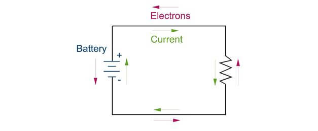
This transfer of electrons creates this voltage potential, which drives the current during discharge as shown in the figure above. The same principal is used when the battery is being charged but in reverse.
Equivalent Circuit
A battery is made up of internal resistance and capacitance. When a battery is placed in-line with a circuit, it is important to account for the internal losses in addition to the charge it provides. The figure below describes the equivalent circuit in a battery. The capacitance is where the charge is stored in the battery. The internal resistance (or losses) is comprised of the resistance through the terminals, electrodes, connections, electrolytes, and other components that the current travels through within the battery. In parallel with the capacitance is the resistance between the plates. This resistance is very small and most likely can be neglected.
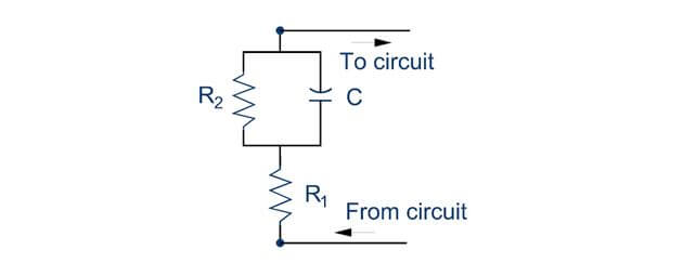
Equivalent Circuit of Battery, where R2 is the resistance between plates and R1 is the internal resistance of the battery.
Types
There are many different types of batteries available for use in the power industry. The most common batteries are briefly described in the following sections. On the PE exam, you should be familiar with the different types of batteries that are most commonly used, but nearly as in depth as if you were a battery manufacturer. You should know the basics about the different types and their advantages/disadvantages. The main skill that you should know is how to select the correct capacity batteries, which will be described in the ratings section. In power engineering, batteries are mainly used for backup power, such as an Uninterruptable Power Supply (UPS), in motor and machine startup, and for alternative energy storage.
Lead Acid Battery
If you do not regularly work with batteries in your field, please look at the following websites and click on the product data for different batteries and see the type of information that is presented. This will give you some additional context on how batteries are rated for the following sections.
Manufacturer's Link: Flooded Lead Acid Batteries
The flooded lead-acid battery was the first battery available and is currently one of the cheapest battery options. In this battery, lead electrodes are separated by a liquid electrolyte, which is typically sulfuric acid. The flooded term describes the battery as being wet and the lead term is used for the electrode and finally the acid is the electrolyte. This results in the name, Lead-Acid Battery and in the link above the specific type of battery, called the Flooded Lead Acid Battery.
The advantages of this type of battery are its low cost and its high peak current output. One disadvantage is the increased maintenance due to the creation of gasses during charging. The fluid will be converted to gasses and will be leaked to the atmosphere during this process, which will require maintenance to refill the electrolyte fluid. Another disadvantage is the safety issue which could be caused by the leaking of the electrolyte fluid upon rupture or if the battery is flipped over.
The information shown on this website is a sample of the material provided in the technical study guide and sample exam. See the STORE to buy the products for continuation on VRLA , Lithium, Ratings, C-Rating, E-Rating, Cycle Life, Temperature Effect, State of Charge and CCA.
Power Supplies
In the “Devices and Power Electronic Circuits” section there is a need for a power source to run these devices and equipment. The most common power supplies in this section are the (1) battery and (2) AC to DC inverter. The battery was previously discussed in 2.0 Batteries and in 4.0 Variable Speed Drives you will learn the key concepts of inverters and how they can be tested on the exam.
AC TO DC INVERTERS
An AC to DC inverter converts alternating current to direct current. The most common way this is done is through the use of rectifiers which will be discussed in 4.0 Variable Speed Drives of this Section.
DC TO AC INVERTERS
A DC to AC inverter converts direct current from alternating current. These types of inverters are used in the power engineering field in PV installations, where the direct current output from a PV module must be converted to AC in order for it to be used in the normal power distribution system. Inverters are also commonly used in an uninterruptible power supply or UPS. A UPS stores energy as a battery, which normally supplies power in DC. However, in order to power electronics, this DC power must be converted to AC.
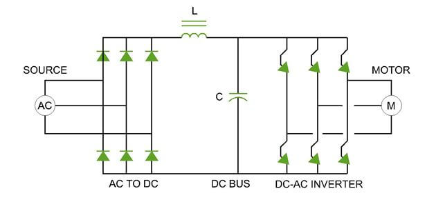
Variable Speed Drives
A big part of the Devices and Power Electronics Circuits section is learning about variable speed drives (VSDs). You should be able to look at a manufacturer’s product data and be able to explain how each part of the variable speed drive works and what happens to the drive during normal operation. The following section will describe the construction of each of the VSD parts, what they each do, and finally how the VSD puts it altogether.
Thyristors, Diodes and IGBTs
The first part of the variable speed drive is the set of diodes.

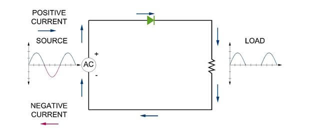
A diode is an electronic device that acts as a switch, allowing current to only flow in one direction. In the figure above, it is conventional for the positive current to flow in the direction of the arrow shown in the diode symbol. There are two parts, (1) anode and (2) cathode, that operate the gate or switch. A diode operates based on the voltage waveform. When the voltage waveform is positive, then the gate is open and current can flow through the diode. When the voltage waveform is negative, then the gate is closed and current is stopped.
Secondly, if the gate is already open and current is flowing through, then the gate cannot be closed. Once current stops and there is no positive voltage, then the gate will be shut.
Diodes are selected based on the peak inverse voltage. Diodes must be rated to handle the maximum negative voltage difference that will be expected in the circuit. If the negative voltage difference is too high, then the diode will be unable to stop current from flowing during the negative voltage part of the voltage waveform.
A thyristor is similar to a diode except there is an additional form of control. The diode is controlled based on the voltage waveform and whether or not it is positive or negative. The thyristor has the same control with respect to the voltage waveform, but it also has an additional gate current control. When the voltage waveform is positive, the thyristor will be ready to release current to the circuit. Once the thyristor receives a gate current then the thyristor will open its gate and release the current. If the thyristor receives a gate current when the thyristor has a negative waveform, then no current will be released. The most common type of thyristor is the Silicon Controlled Rectifier (SCR).

Insulated Gate Bipolar Transistors (IGBT) are similar to thyristors, except instead of a gate current pulse, IGBTs are activated by a continuous supply of gate voltage. You should be familiar with all three of these devices for the PE exam, since these devices make up the construction of variable speed drives.
Rectifiers
Thyristors and diodes are used in power circuits to convert AC to DC and DC to AC. The circuit that arranges thyristors and diodes to convert AC to DC is called a rectifier. On the exam you should be familiar with the main rectifier circuits. These circuits are half-wave, full-wave and full-wave with capacitor.
Half-Wave Rectifiers
In a half wave rectifier, alternating current (AC) is converted to direct current (DC). When the current is in the positive half of the waveform, the current is allowed through the diode. However, in the negative half of the waveform, the current is blocked by the diode. This results in the load only seeing the positive humps of the waveform as shown in the right half of the figure. Thus the current is now DC, since there is no alternating between positive and negative.
The information shown on this website is a sample of the material provided in the technical study guide and sample exam. See the STORE to buy the products for continuation on Full-Wave Rectifiers, DC Bus Ripple, Full Wave Rectifer with Capacitor, Inverters and finally Variable Speed Drives.
Controls
Controls in the power industry can cover the following areas, (1) Power Flow and (2) Generator/Motor Control. The flow of power is controlled through switches and relays. These devices ensure that power is directed correctly and safely. Generators and motors are controlled to optimize efficiency and safety based on various situations. For example, during periods of low load, generators should shut off in a desired order.
Relays and Switches
A relay is a switch that is operated based on electronic or electromechanical signals. Relays are covered in detail in Section 8.0 Protection.
Relays and Switches
A programmable logic controller (PLC) is a controller that provides more automated control to relays, devices and switches. A controller can take IF, THEN statements and automate the flow of power and the control of generators and motors based on pre-programmed situations.