![]()
Engineering Pro Guides is your guide to passing the Mechanical & Electrical PE and FE Exams
Engineering Pro Guides provides mechanical and electrical PE and FE exam technical study guides, practice exams and much more. Contact Justin for more information.
Email: contact@engproguides.com
EXAM TOOLS
Electromagnetic Devices
for the Power P.E. Exam
Introduction
The section, Electromagnetic devices accounts for approximately 6 questions on the Power Electrical PE exam. The Electromagnetic Devices section covers all different types of transformers and reactors. Transformers and reactors generate current through electromagnetic fields, hence the term electromagnetic devices. Transformers are the biggest topic from this section on the exam, because of the many types of transformers and the ease in which questions can be constructed for the exam. Transformers also overlaps with the Measurement & Instrumentation section and the Power System Performance section.
The information shown on this website is a sample of the material provided in the technical study guide and sample exam. See the STORE to purchase these items.
Transformers
Transformers are a type of electromagnetic device that uses the principals of electromagnetic induction to convert one voltage to another; i.e. any time you want to change the voltage in an electrical system, you use a transformer. There are two sides of a transformer, the primary and the secondary. The side of the power source is typically denoted as the primary, while the secondary is the side of the transformed voltage. The power and frequency across a transformer remains the same, while the primary and secondary voltages and currents will change, following the relationship P = I*V for a single phase transformer.
Transformers are rated in apparent power, kVA, and the primary and secondary voltages. A step-up transformer is a transformer that increases the secondary voltage. A step-down transformer reduces the secondary voltage.
One major application of a transformer is in power distribution. By increasing the voltage in a distribution line and reducing the current, the losses through long transmission lines (Vlosses = I*Zline losses) can be reduced. Although DC power is more efficient than AC power, AC power is used more commonly than DC because the principals of transformers will only function under AC current.
Types of Transformers
Transformers are most commonly used in the following applications.
- Power: Power transformers are large in size and used in high voltage applications (>33kV), typically at the generator and at substations.
- Distribution: These transformers are used at the distribution end of a system, downstream of the substation (<33kV). The transformer provides the appropriate voltage to the loads.
- Auto Transformer: An autotransformer uses a single winding instead of two. It is cheaper in construction and used for lower ranges of voltage changes. Auto transformers are discussed in the next section.
- Measurement: Measurement transformers include current transformers and potential (voltage) transformers which are used in measuring the current and voltage, respectively, within a system. Further application of these devices are described in the Measurement and Instrumentation section of this book.
- Protection: High accuracy measurement transformers are used in the protection system to trigger a protection scheme at specific settings.
This section focuses on power and distribution type transformers.
Construction
A transformer is made up of a metal core and two windings, or wires that wrap around the core. The core itself is made up of thin laminates with insulation between each layer to electrically isolate the laminates. Using thin laminates instead of one solid core reduces the amount of eddy current losses through the core. Eddy current losses are explained in the Real Transformer section.
The basic operation of a transformer begins with an AC current that is sent through the primary winding. As the current flows through the wire and around the core, a magnetic flux is created through the core. The magnetic flux in the core then induces current through the secondary windings to produce AC current at a different voltage, which is specified by the number of turns in the windings. This will be discussed in the next section.
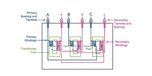
Basic construction of a three-phase transformer, which is made up of three single-phase transformers. The copper windings can be seen on the transformer core. These windings are then wired to connection points at the exterior of the transformer. These points are called terminals. The bushings are located at the terminals. They are used to insulate the wires that pass through the transformer enclosure, preventing the charge in the wires from hitting the grounded enclosure.
Construction Types
There are various types of transformers, which can be seen on any of the popular manufacturers’ websites. For the purposes of the exam, you should just be familiar with the names and how the types are different only for context of problems. The exam most likely will not test you on the construction differences of the different types of transformers. The exam will test you on the different transformer arrangements which are discussed later.
Manufacturer's Link: Schneider Electric Transformers
The various construction types are broken up into low voltage, medium voltage and high voltage. The transformers can either be liquid filled or dry type. Each transformer will have inefficiencies and these inefficiencies will cause heat within the equipment. The dry/liquid types describe the method in which this heat is dissipated. A liquid type uses a liquid to cool the equipment, while a dry type uses air. The dry type will be much larger since it takes a higher volume of air to provide the same amount of cooling as a liquid.
Tap Setting
Tap settings are used to slightly adjust the voltage ratings on transformers. In real world conditions, voltage drops will occur in transmission lines or the distribution will provide higher voltages than required, causing the voltage at the transformer to be different than it is rated for. A tap will compensate for this variance and allow the secondary side to deliver the appropriate voltage. For example, a 480V/120V transformer may actually be receiving 450V, causing the secondary voltage to be 116V. Using a +2.5% tap at the primary side will raise the primary voltage to 477V, effectively raising the secondary voltage to 119V, closer to its rated 120V.
Taps are terminals that are connected to the windings of the transformer. It can either be located on the primary or secondary winding, but is usually located on the high voltage side, where the current is lower. They are installed such that a whole number turn is either added or subtracted from the windings to adjust the turns ratio, and therefore the secondary voltage of the transformer. Depending on the size of a transformer, there will be a certain amount of windings per voltage, which will determine the % tap settings available. Taps will typically not change the power rating of the transformer, but will vary the current. This is known as a full capacity tap.
Ideal Transformers
In an ideal transformer, it is assumed there are no losses: the apparent power that enters the primary side of the transformer is equal to the apparent power that leaves the secondary side of the transformer. This conservation of energy is the same for the real power and reactive power.

The primary purpose of the transformer is to change the voltage. The change in voltage is related to how many times the wires wrap around the coil, as shown in the equation below, where N is equal to the number of windings (also known as the turns) around the coil.

The figure below is a typical schematic of a transformer used in circuit analysis.
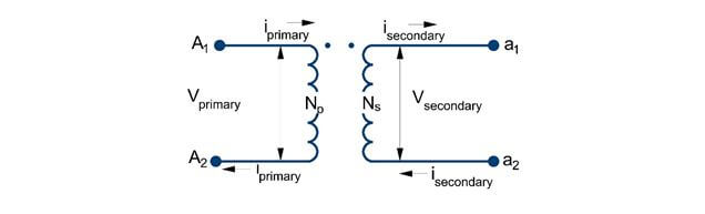
Transformer schematic, where A1 and A2 are the primary terminals and a1 and a2 are the secondary. N indicates the number of turns in each winding and V and I are the voltages and currents in the primary and secondary side of the transformer. The dots at the top of each winding indicate the positive ends of the voltages at each transformer coil.
The ratio between the primary and secondary windings is known as the turns ratio, a.
The information shown on this website is a sample of the material provided in the technical study guide and sample exam. See the STORE to buy the products for continuation on Transformers including the following topics:
- Transformers and Ohm's Law
- Real Transformers
- Real Transformers Equivalent Circuit
- Real Transformers and Coil Losses
- Real Transformers and Core Losses
- Transformer Efficiency
- Transformer Short Circuit Test
- Transformer Open Circuit Test
- Transformer Impedance
Transformer Arrangements
The next parts of this section will cover the various arrangements for transformers. On the PE exam, you can refer to these arrangements and the equations to help you quickly answer questions. Often times it can be confusing to have to reconstruct the arrangement and determine how the line and phase voltages/currents are related for the various arrangements. This section will help to alleviate that confusion and speed up your problem solving.
The information shown on this website is a sample of the material provided in the technical study guide and sample exam. See the STORE to buy the products for continuation on Transformers including the following topics:
- Delta-Wye Transformer
- Delta-Delta Transformer
- Wye-Delta Transformer
- Wye-Wye Transformer
Auto Transformers
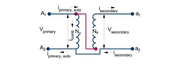
Auto-transformers are a special type of transformer that is used to make small incremental changes in voltage. An autotransformer starts off in construction similar to a normal transformer except the end terminals are wired differently, such that there is only a single winding.
Step-Up Auto Transformer
The below figure shows a normal transformer with primary and secondary windings shown, except the end terminals are wired differently. The magenta line shown connecting the primary entrance to the secondary entrance is the difference between a step-up autotransformer and a normal transformer.
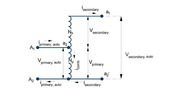
The next figure is the previous figure but drawn differently. Take some time to see how the two figures are exactly the same.
In the step-up auto transformer the following equations can be used to find the currents in the circuit for a single phase transformer.

The voltage of the auto transformer can be related to the voltage of the re-circuited transformer in the previous figure.

The power of the original transformer can also be used to find the primary and secondary currents. The equations are for a single phase transformer.

The information shown on this website is a sample of the material provided in the technical study guide and sample exam. See the STORE to buy the products for continuation on Step-Down Auto Transformers
Reactors
A reactor is basically an inductor as discussed in the circuits section. An inductor physically looks like a conductor wrapped in a coil. As current travels through a coil, a magnetic field forms around the inductor (reactor).
The inductance of a reactor is found through the equation above. The inductance value is dependent upon the construction of the inductor and most dependent upon the number of turns in the conductor. The more turns, the larger the inductance. An inductor creates impedance because it creates an opposing voltage based on the inductance value and the change in current.
As you can see, the change in current (alternating current) will create a voltage drop that is directly related to the inductance value. When a circuit is first started up, there will be a large change in current over time as the amount of current increases from 0 to the rated value. Thus, there will be a large opposing voltage drop that will also oppose the flow of current, which will thereby limit any large inrush of current.
Line/Load Reactor
A line reactor is an inductor that is located in series between a power source and a load. The line reactor will be charged and will create the opposing voltage that will limit the amount of current going to the load.