![]()
Engineering Pro Guides is your guide to passing the Mechanical & Electrical PE and FE Exams
Engineering Pro Guides provides mechanical and electrical PE and FE exam technical study guides, practice exams and much more. Contact Justin for more information.
Email: contact@engproguides.com
EXAM TOOLS
Power - Measurement & Instrumentation
Measurement & Instrumentation - 6 of 80 Problems
The section, Measurement & Instrumentation, accounts for approximately 6 questions on the Power Engineering, Electrical PE exam. Measurement and Instrumentation is focused on the equipment and the use of the equipment to measure, current, voltage, resistance, power and power factor. This topic is a good example of how the exam focuses on the application of electrical concepts rather than on theory. In this section you will learn about current transformers, potential transformers, watt meters, volt meters, ammeters, ohmmeters, mega-ohmmeters and ground testing techniques.
There are only six questions on Measurement and Instrumentation and this topic is relatively easier to grasp compared to the other more complex concepts on the NCEES outline. The exam problems in this section should be simple, so once you have completed this section and the white papers, please focus on the other more difficult topics.
The information shown on this website is a sample of the material provided in the technical study guide and sample exam. See the STORE to purchase these items.
Instrument Transformers
Instrument transformers use the transformer concept to step down current or voltage into safe and easily measurable values. There are two types of instrument transformers, (1) Current Transformers or CTs and (2) Voltage Transformers or VTs. These instrument transformers are used to measure current and voltage. Electrical systems use these current and voltage values to inform electrical operators of status and these values are also used to trigger protection devices. As discussed throughout this book, the PE exam tests your application of engineering knowledge, thus you should be familiar with the common, current instrument transformation knowledge used in practice by manufacturers and engineers in the power field. One of the best free resources on instrument transformers has been produced by General Electric, please read through this white paper for additional background information on instrument transformers.
General Electric - Instrument Transformer Basic Technical Info and App
Current Transformers
A current transformer or CT is located in series with the load and is typically donut shaped. The line current travels through the CT and this current generates a current in the secondary. This current is then measured by an ammeter. A CT uses a step up voltage transformer to increase the voltage within the secondary current, which reduces the current to manageable values, typically in the range of 0 to 5 amperes. Then an ammeter in the secondary current is used to measure the secondary current. This measured secondary current is directly related to the primary current, such that when the primary current is increased, then the secondary current is increased and vice versa.
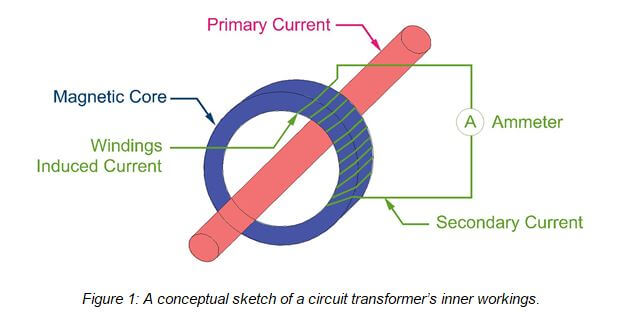
The figure above shows multiple turns on the secondary side of the circuit and only one turn on the primary side of the instrument transformer. This further enforces the idea that the circuit transformer is a step-up voltage transformer. For the PE exam, you should be familiar with the application of circuit transformers and how to select a circuit transformer. If you look at manufacturer’s websites, like General Electric, then you will notice that circuit transformers are provided with specifications in terms of either Turns Ratio or Current Ratio. On the exam, you should be very careful that you are using the correct ratio.

See technical study guide for continuation.
Potential Transformer
A potential transformer or PT is used to measure the voltage in a system. The PT will step down the voltage to a safe voltage and then the PT will use a voltmeter to indicate the voltage in the secondary. This secondary voltage is directly related to the primary voltage through the turns-ratio of the transformer.

See technical study guide for continuation.
Watt-Meters
A watt meter is a combination of a current coil and a potential coil that measures watts. The current coil is connected in series with the wire carrying current and this coil measures the current. The potential coil is installed between two current carrying wires and measures the phase to phase voltage.
The number of watt meters required to accurately measure the power in a multiple wire system is governed by the below equation. If you have a three-wire system, then you will need two watt meters and if you have a four-wire system, then you will need three watt meters.

One Watt Meter Method
The one watt meter method can only be used for single phase power. In practice, some engineers may use the one-watt meter method for balanced three phase power. However, this will not produce accurate results if the loads are unbalanced.
Two Watt Meter Method
The two watt meter method can only be used for three phase power with three wires. Thus this method can only be used for delta systems and wye systems with no neutral.
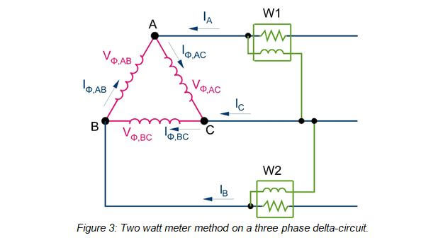
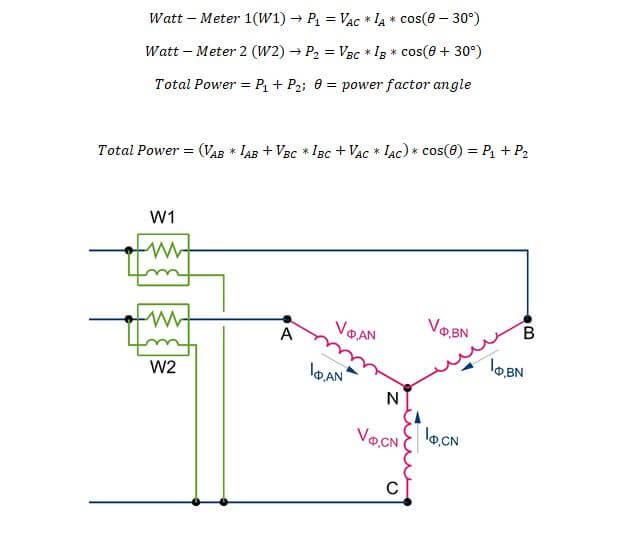
In the two watt meter method, the current through two phases is measured. In the previous figure, the current through phases A and B are measured. Then the voltage between these phases and the other phase is measured. In the previous figure, the voltage different between phases A-C and B-C are measured. On the exam, you should use the following equations to calculate total power, where total power is equal to the sum of the power measured at watt-meter 1 and watt meter 2. The power measured at the watt meters is found by multiplying the current, voltage and the power factor with a 30 degree phase shift positively or negatively.
Three Watt Meter Method
See technical study guide for the Three Watt Meter Method.
VOM Metering
The term VOM refers to Volt-Ohm-Milli-ammeter, which is another name for a multimeter. These are the handheld meters that are manufactured by Fluke and Simpson. Please see the Fluke website at the link below if you are not familiar with these devices.
On the PE exam, you should be familiar with this tool and how it is used. However, by the nature of this device, it will be very difficult to provide a test question that is solely dedicated to VOM metering. It is easier to use this device as a part of an exam question. For example, the exam may present a complex circuit where they are testing your understanding of line and phase currents. Then the exam may ask you, “What will your VOM meter read at a certain point if your leads are placed at location X and location Y?”
A VOM meter consists of a volt meter, ammeter and an ohmmeter in one device. Each individual mode of operation will be discussed in the following sections. VOM meters also may have other functions as shown on the Fluke website. These devices can measure ampere-hours, power factor, harmonics and much more. According to the NCEES website, there are only 6 questions in the Measurement and Instrumentation section, so use your time wisely and focus on the concepts that are testable and most common, like the CT, PT, watt-meter and the ground resistance testing subjects.
See technical study guide for discussion on Voltmeter, Ammeter, and Ohm Meter.
Insulation Testing
The purpose of insulation on conductors, transformers, generators, motors, etc. is to ensure that current travels through the conductor and does not create a potential difference between the metal part of the conductor or equipment and anything else. For example, if a conductor is carrying 480 V and its insulation exposes the metal part of the conductor, then there will be a potential difference of 480 V and the air, with little impedance. If a person walks near a conductor then the potential difference between the exposed metal and the person will be 480 V. If the distance between the two is minimal then current will arc from the exposed metal conductor to the person. If the voltage is much larger, like 13.8 KV then the person could be a further distance away and current will still arc to the person.
See technical study guide for more on Insulation Testing.
Ground Resistance Testing
One of the best sources for ground resistance testing and also grounding design is IEEE. It is recommended that you have IEEE 81 as a reference or to learn more about grounding.
Soil Resistivity Testing
The first thing that should be tested when designing a grounding system or when testing a grounding system is to test the soil resistivity. The various manufacturers of soil resistivity equipment testers like Fluke have whitepapers on the process of testing soil resistivity. This information is very good to get a practical idea of how soil resistivity is conducted, if you do not regularly conduct soil resistivity tests.
For the exam, you should be familiar with the following equation and the basic idea of soil resistivity resting. In a soil resistivity test, conductors are driven into the ground at certain distances and these conductors are connected to a voltage supply (soil resistivity tester). Then a known current is run through the test conductor and the voltage difference between two points will provide a quick calculation for the resistivity of the soil in between the driven conductors. The most common method of testing is the 4-point method, which is shown in the figure below.
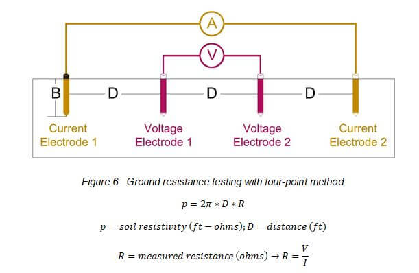
You can only use the previous equation when D is sufficiently larger than B, on the order of 20 times B.
See technical study guide for more detail Ground Resistance Testing.