- HOME
- FE EXAM
- PE EXAM
- DESIGN TOOLS
- COURSES
- STORE
- ABOUT
- CONSULTING
![]()
Engineering Pro Guides is your guide to passing the Mechanical & Electrical PE and FE Exams
Engineering Pro Guides provides mechanical and electrical PE and FE exam technical study guides, practice exams and much more. Contact Justin for more information.
Email: contact@engproguides.com
EXAM TOOLS
Rotating Machines
for the Power P.E. Exam
by Justin Kauwale, P.E.
Introduction
The section, Rotating Machines, accounts for approximately 10 questions on the Power Engineering, Electrical PE exam.
The rotating machines section on the PE exam focuses on two main types of machines, (1) Synchronous machines and (2) Induction machines. These two types of machines are important in electrical power engineering, because these two machines define the primary sources and loads for AC power. Induction motors are one of the largest loads for electricity and synchronous generators are the leading power sources for AC power.
In order to do well on rotating machines exam problems, you should understand how electricity is generated through a synchronous generator and how electricity is used by a motor. You should be able to follow the flow of electricity through the equivalent circuit of a generator and motor.
The exam also does have miscellaneous questions on starting methods, speed and torque. These three terms are also discussed in this section.
The information shown on this website is a sample of the material provided in the technical study guide and sample exam. See the STORE to purchase these items.
Synchronous Machines
A synchronous machine is a machine that rotates at the same frequency as the alternating current. This frequency is called the synchronizing frequency and in the USA, this frequency is 60 Hz. An induction machine rotates at a frequency slightly less than this synchronous frequency.
This section will primarily focus on synchronous machines and the following section will focus on induction machines.
Both synchronous machines and induction machines can then be separated into two main types of machines, (1) Generator or (2) Motor.
- Generator: A generator uses the mechanical energy from rotation to produce alternating current electrical energy.
- Motor: Motors use alternating current electrical energy to produce mechanical energy in the form of rotation.
These two types of machines are discussed in further detail in this section, but first you should understand the general construction of a synchronous machine.
Construction
There are four main parts of a rotating machine.
- Mechanical Stator: The stator is the stationary part of the synchronous machine.
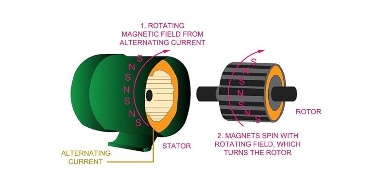
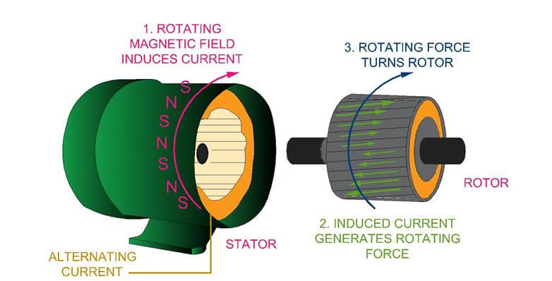
- Electrical Field Winding: A winding is another term for electrical coil. The field refers to the rotating magnetic field component. In a motor, the stator receives three-phase alternating current which creates the rotating magnetic field and in a generator, the rotor is rotated to create a rotating magnetic field.
- Mechanical Rotor: The rotor is the rotating part of the synchronous machine.
- Electrical Armature Winding: The armature refers to the current producing component. In a motor, the armature winding in the rotor receives a magnetic field from the stator, which generates electricity in the armature winding that turns the rotor. In a generator, the rotor is turned to develop a rotating magnetic field that generates current in the armature winding located in the stator.
Synchronous Speed
The synchronous speed of a rotating machine is defined by the equation below.

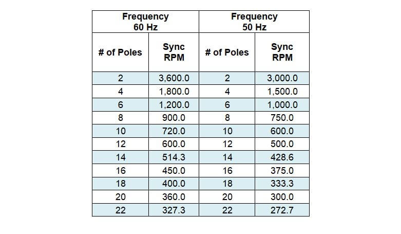
In practice, the speed of motors is typically 1,800 RPM, with some motors up to speeds of 3,600 RPM. A lower speed is often desired because of the decreased wear and tear on a motor due to the lower number of rotations. Generators also follow the same principle and can vary in speeds as high as 3,600 RPM down to 360 RPM and lower. The following table shows the corresponding synchronous speed in revolutions per minute as a function of the number of poles and frequency. Notice that the number of poles will always be even since there must always be a north pole and a corresponding south pole.
Synchronous Generator
A generator converts mechanical energy into electrical energy. Mechanical energy is used to spin the rotor of a generator which in turn generates power through the stator. To accomplish this, a DC current, known as the field current, flows through the windings of the rotor to produce a magnetic field. Mechanical power, or the prime mover, is used to spin the rotor. A prime mover can be a turbine that spins via steam, fuel, or hydro energy. As the magnetic field in the rotor spins within the stator, AC voltage and armature current is induced in the stator windings, producing AC power.
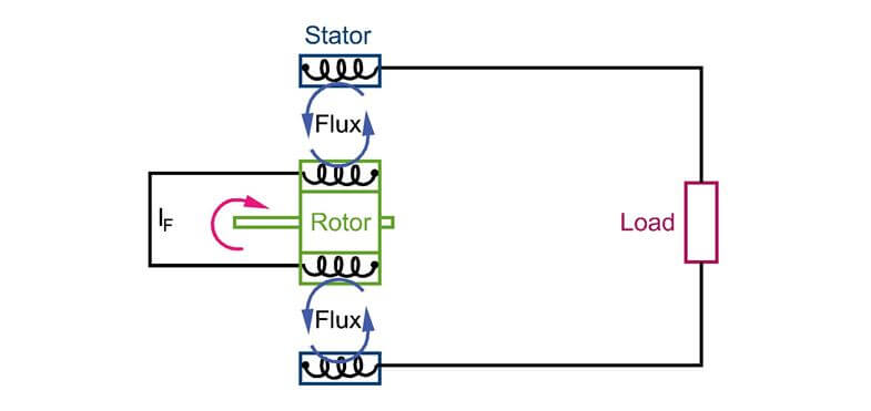
The field current affects the voltage magnitude and the rotor speed affects the phase angle of the voltage.
Equivalent Circuit
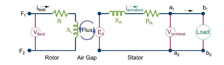
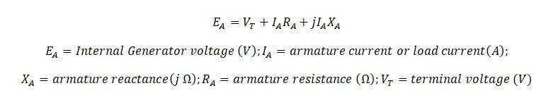
The following figure shows the equivalent circuit of synchronous generator. Understanding the equivalent circuit and the phasor diagrams that represent the circuit for a particular system will help you decipher most generator questions. We begin by the overall equivalent circuit. The circuit represents the rotor and the stator of the generator, which is separated by an air gap, where the magnetic flux is induced from the rotor to the stator.
Rotor: A DC field current is applied at terminals F1 and F2 at the rotor. The field current flows through the internal resistance (R) and inductance (XL) of the rotor coil. Included within the resistance is an adjustable resistor that is used to change the field current.
Stator: The magnetic flux produced by the rotor induces a voltage (EA) at the stator. This is the generator voltage, also known as the internal voltage. The armature current (IA) is the current flowing within the generator at the stator. There is a voltage drop through the stator due to the armature reactance and resistance. The armature resistance is usually small. The resulting voltage at the terminals (VT) can be visualized as the voltage available at the wires leaving the generator.
Synchronous generator questions involve finding one of the variables in the below equation.
In a synchronous generator there are two types of load conditions that you should understand, (1) lagging and leading loads. As previously discussed in other sections, lagging and leading is in terms of current on the phasor diagram. The following sections will take you step by step through the phasor diagram for these two conditions and ultimately how to apply the equation above.
Synchronous Generator – Leading Power Factor
In this condition, current is leading the voltage. When the power factor is leading, the generator is said to be under-excited, where the real component of the generator voltage (EA) is less than the terminal voltage. In this situation, the generator is receiving reactive power from the system, similar to an inductor, i.e. reactive power is negative. In normal conditions, real power is always supplied from the generator. See the phasor diagram for more details.
The information shown on this website is a sample of the material provided in the technical study guide and sample exam. See the STORE to buy the products for continuation on Synchronous Machines including the following topics:
- Synchronous Generator Leading Power Factor Equivalent Circuit
- Synchronous Generator Lagging Power Factor Equivalent Circuit
Induction Machines
Induction machines are most commonly used as induction motors and throughout this section, the term induction motors will be used. These inductions motors are also called asynchronous motors, because these motors run at a speed lower than synchronous speed. Induction motors can be either single phase or three-phase. There are various types of motors within the family of induction motors, but this is beyond the scope of the PE. You should understand the equivalent circuit, slip, voltage regulation and voltage unbalance.
Construction
An induction machine, similar to a synchronous machine, has a stator and a rotor. Most routers are the squirrel cage type rotor. In an induction motor, the stator is stationary and the rotor rotates and the two parts are separated by a small air gap.
The stator contains steel laminations and copper windings. Current passes through the winding (twisted electrical coils) and produces an alternating flux that revolves at a speed in accordance with the frequency of the alternating current. This rotating magnetic field rotates at synchronous speed. Synchronous speed was discussed in the synchronous machines section. However, this is an induction machine and an induction machine does not operate at synchronous speed. The rotating magnetic field first induces a current in the rotor conductors. These conductors are shorted loops of metal. This induced current travels in these conductors and will create a force that causes the rotor to rotate. The rotor will rotate at a speed that is slightly less than synchronous speed and the difference between the actual speed of the rotor and synchronous speed is called slip.
The information shown on this website is a sample of the material provided in the technical study guide and sample exam. See the STORE to buy the products for continuation on Synchronous Machines including the following topics:
- Slip
- Actual Speed vs Synchronous Speed and Slip 50 and 60 HZ Tables
- Induction Motor/Generator Equivalent Circuits
- Voltage Regulation
- Voltage Unbalance
- Characteristics under Various Loading Conditions
Speed-Torque
The torque of a motor/generator will be dependent on the speed and power of the motor. This equation is shown below.

The torque found in the above equation is the rated torque, meaning the torque at the nameplate value of the motor or generator. When a generator’s torque rotation is in the same direction as the rotational speed of the generator, the generator delivers power. When a motor’s torque rotation is in the opposite direction of the motor, then the motor is receiving power.
However, a motor/generator needs to start from rest and be increased to the rated speed. This increase in speed is a difficult electrical process, especially for very large motors which can be taxing upon an overall power system. You should understand how a motor starts, which is explained in the next part and the relationship between speed and torque during this starting process.
The following graph best explains the relationship between speed and torque for motors and generators. The locked rotor torque is torque developed during start-up and corresponds to a rotor speed of 0 RPM. You can imagine a motor running and its rotor spinning and then grabbing the rotor and instantly stopping the rotor. The torque required to hold the rotor at 0 RPM describes the term, locked rotor torque. This torque is also known as start-up torque. The start-up torque or locked rotor torque can be as much as 300% of the actual rated torque.
The information shown on this website is a sample of the material provided in the technical study guide and sample exam. See the STORE to buy the products for continuation on Torque vs Speed Graph, No Load Torque, Locked Rotor Torque, Pull-Up Torque and Breakdown Torque.
Starting Methods
A popular source for starting methods for new power engineers is the ABB website, which is one of the leading manufactures in the motor and generator industry. A popular product that is used by power engineers is the starter. There are many products available for starters, but this guide focuses on the most commonly used starters.
When discussing starting methods, you should be familiar with the following terms and equations, Torque, Inrush Current and Starting Voltage.
Torque
Torque is the rotational force provided by the rotor.
Inrush Current
Inrush current is the maximum, instant current drawn by a motor when it is turned on. This inrush current value can be 6 to 8 times greater than the actual, full load current. This large current is used to charge and create the magnetic field, but once it is created and the rotor is moving, then the large current is removed and the current settles at the rated current.
In a stall condition, the amount of current drawn by an induction motor is determined by the frequency and magnitude of the applied voltage and the impedance of the motor.
The information shown on this website is a sample of the material provided in the technical study guide and sample exam. See the STORE to buy the products for continuation on starting methods including the following topics:
- Across the Line Starter
- Reduced Voltage Starters
- Variable Speed Drive as a Starter
- Power Flow Between Voltage Sources