- HOME
- FE EXAM
- PE EXAM
- DESIGN TOOLS
- COURSES
- STORE
- ABOUT
- CONSULTING
![]()
Engineering Pro Guides is your guide to passing the Mechanical & Electrical PE and FE Exams
Engineering Pro Guides provides mechanical and electrical PE and FE exam technical study guides, practice exams and much more. Contact Justin for more information.
Email: contact@engproguides.com
EXAM TOOLS
Engineering Science & Mechanics
for the Machine Design & Materials P.E. Exam
by Justin Kauwale, P.E.
Introduction
The Engineering Science & Mechanics section accounts for 10 questions on the Machine Design & Materials PE Exam. These questions can cover topics, statics and dynamics. The statics topic on the NCEES exam is similar to a common statics college engineering class. Statics is the study of components at equilibrium, which means the components are at rest or at zero acceleration. This topic includes vectors, free body diagrams, moments, reaction forces, first moment of area and second moment of area. These concepts and skills are used to solve problems on pulleys, cables, springs, beams, etc.
Dynamics is the focus of components that have acceleration. The dynamics topic covers both kinematics and kinetics. Kinematics includes the velocity, accelerations and displacement of components. Kinetics includes motion as well, but specifically motion in relation to forces.
A lot of the material presented in this section should have been covered in your engineering classes. But it may have been a while since you learned this material. This section will give you a refresher and will help you to remember those skills and concepts from college/university, especially the skills and concepts that are applicable to the PE exam. If you find yourself struggling with the material, then please refer back to your engineering textbook on engineering mechanics or purchase the reference on this topic presented in References.
The information shown on this website is a sample of the material provided in the technical study guide and sample exam. See the STORE to purchase these items.
Statics
As previously stated, statics is the study of mechanical components at equilibrium, which means the components have zero acceleration or are at rest. The material presented on statics focuses on the key equations and skills necessary to complete the possible problems within this topic on the PE exam.
Vectors
Vectors are used to visualize forces and moments in Engineering Mechanics. Vectors describe the magnitude and direction of force or moment. On the PE exam you must be able to translate words or diagrams into force/moment vectors and you must be able to add/subtract vectors and multiply/divide vectors by scalars.
Vectors can either be represented in a rectangular form or a polar form. The rectangular form consists of an x-component and a y-component. These values are used to represent the magnitude in the x and y directions. In real applications, there will also be a z-component, but for the purposes of the exam you most likely will only need the x and y components. The polar form is shown as a magnitude and an angle. The magnitude describes the length of the vector while the angle determines the direction.
This standard provides a table that shows the different types of lines shown on engineering drawings. Please see below for the various types of lines and how/when these lines are used. It is not necessary to purchase this book for the exam.
Rectangular Form
The rectangular form is shown as, x plus the y component. The y component is shown as j and the x component is shown as i.

The rectangular form is used when adding and subtracting vectors and follows the same rules as normal addition and subtraction, where only like terms can be added and subtracted. For example, “Example A” plus “Example B”, is solved with the following process.

The rectangular form can also be understood via a graphical format, where the x-axis represents the real component and the y-axis represents the imaginary component.
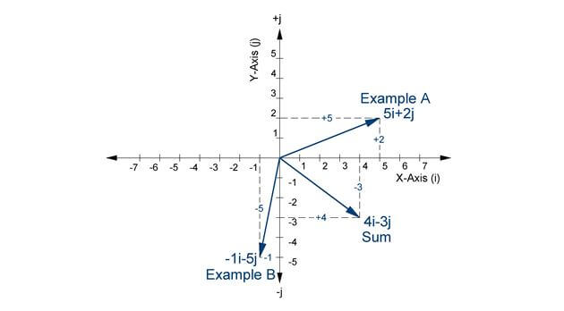
Figure 1: Example “A” vector, example “B” vector and the sum of the two vectors is shown in the above graph.
Polar Form
The polar form is best understood in its graphical format. The format consists of a phasor magnitude at a phasor angle relative to the x-axis.
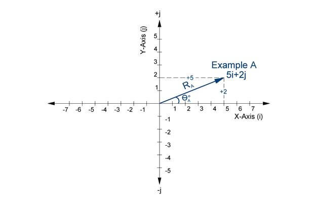
Figure 2: A phasor shown in both polar and rectangular form.
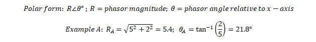
In the above example, the polar form is converted from the rectangular form by using the Pythagorean Theorem to find the radius (i.e. the magnitude) and the inverse tangent to find the angle. The polar form is not typically used for adding or subtracting, but it is used for multiplication and division. When multiplying or dividing two polar forms, you must multiple/divide the radiuses and add or subtract the angles. If the polar forms are being multiplied, then you must add the angles and if you are dividing one polar form from another then you subtract the divisor from the dividend.

Converting Polar and Rectangular Forms - Calculator
During the exam, you will need to convert from polar form to rectangular form and vice versa. You will need to convert between the two forms in order to carry out multiplication/division or addition/subtraction. You should be able to quickly convert between the forms with your calculator. This will help to save you time for more difficult tasks during the exam.
You should use the most advanced calculator allowed by NCEES. The calculators allowed by the NCEES are shown below.
- Casio: All fx-115 and fx-991 models (Any Casio calculator must have “fx-115” or “fx-991” in its model name.)
- Hewlett Packard: The HP 33s and HP 35s models, but no others
- Texas Instruments: All TI-30X and TI-36X models (Any Texas Instruments calculator must have “TI-30X” or “TI-36X” in its model name.)
Casio FX-115, Casio FX-991, HP35 and TI-36 are all decent calculators that can do multiple calculation steps without having to use the memory function in the calculator or without having to write down numbers in between steps. However, the Casio and TI models are the cheapest. Whichever calculator you decide on using, make sure that you use the calculator during your studying so that you can be well versed in the use of your calculator prior to taking the exam.
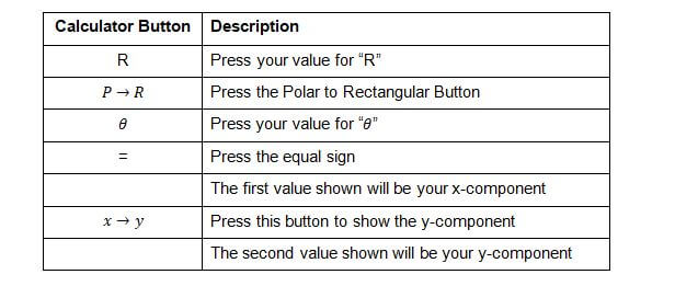
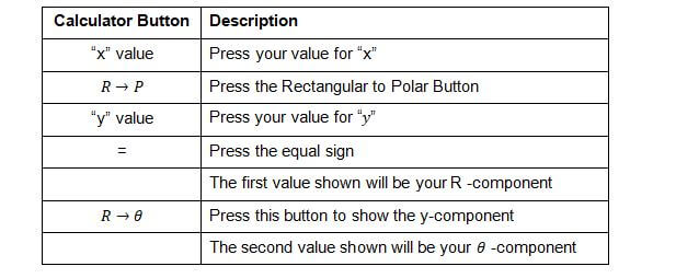
The following are the basic steps in converting from polar form to rectangular form. The above calculators also have the option of adding/subtracting and multiplying/dividing multiple polar or rectangular numbers. Please be sure to learn this skill, because you will use the skill throughout the exam.
Convert Polar to Rectangular
Convert Rectangular to Polar
The Casio FX-115 also has a complex mode which allows you to add/multiply complex numbers in various forms and easily converting the results between rectangular and polar. The stored lines of calculations and the various functions, including matrices and integrals make this calculator one of the favored among test takers.
Force
Force is the action that pushes or pulls an object. The force can be invisible like gravity, electrical or magnetic. In machine design, the only invisible force that is tested is gravity. In addition, visible forces due to pulleys, gears, hydraulics and much more are tested on the machine design exam.
One of the first set of concepts you learn in Statics are Newton’s Three Laws of Motion. The application of these laws is tested on the exam and it is assumed that you learned these laws and other fundamental Statics concepts in college/university.
First Law: The first law states that an object at rest or at constant velocity (zero acceleration) will remain that way, until an unbalanced force acts upon the object.
Second Law: The second law states that an object subject to an unbalanced force will be subject to an acceleration that is directly proportional to the unbalanced force and inversely proportional to the object’s mass.
Third Law: The third law states that objects that are in contact with each other will experience a force opposite the subject force acting upon the object. This force is called the reaction force. This law is useful in the beam type problems.
The units of force are usually given in US customary system of units for the PE exam. This means that force is measured in pounds (lbs). Mass is given in terms of slugs ((lb*s^2)/ft). However you should also be familiar with the International System of Units (SI). Force is measured in Newtons ((kg*m)/s^2 ) and mass is given in terms of kilograms (kg). Make sure you know where to find the conversions between the two sets of units in your Unit Conversion Book.
Free Body Diagram
On the exam, there will be questions with diagrams and sometimes without diagrams. But one thing that will not be provided at any time on the exam will be the forces and directions of these forces. You will need to be able to draw a free body diagram of the forces acting upon an object in order to create the equilibrium equations that you will need to solve the problems. The first step is to assign a frame of reference and assign which direction is positive and negative. Typically, forces acting in the left direction (x-axis) and down direction (y-axis) and out of the page (z-axis) are assigned a negative force. Forces acting in the right direction (x-axis), up direction (y-axis) and into the page (z-axis) are assigned a positive force.
Equilibrium
If an object is not moving, then the object is in equilibrium. This means that the forces acting upon an object in the x, y and z directions will sum to equal zero. On the exam, you can use these equilibrium equations to solve for the unknowns.

Springs
A good example of equilibrium equations are the equations developed for spring applications. When an external force acts upon a screen, there is an equal and opposite reaction produced by the spring. The spring force is a function of the stiffness constant of the spring and the displacement produced within the spring.
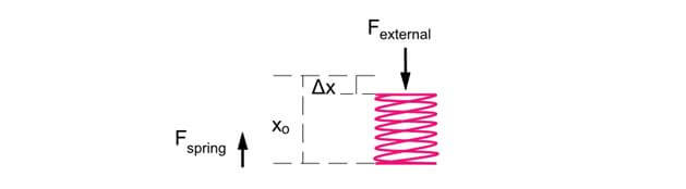
Figure 3: If the spring is not moving, then the external force will be equal to the spring force. The spring force will be equal to the spring’s stiffness value multiplied by the displacement.
Pulleys and Cables
Another example of developing equilibrium equations can be shown for pulleys and cables. A pulley is a wheel on an axis that is securely attached to a surface. The pulley is used to change the direction of the cable’s force. A cable is used to transmit force (tension) from one end to another end of the cable. The important thing to remember is that the tension in a cable is the same at any location along the cable.

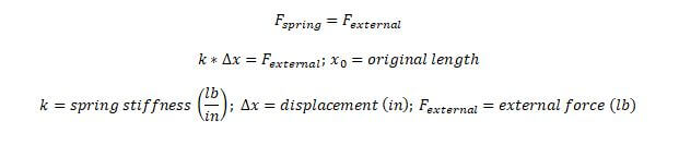
Figure 4: The tension in a cable is constant. Ta equals Tb.
At first glance, the downward forces do not balance out and it would appear that the cable and pulley are not in equilibrium. However, the pulley is securely attached to the upper surface. This produces reactionary forces that balance out the downward forces as shown in the free body diagrams below.
Figure 5: In this figure the downward forces acting on the pulley are due to Ta and Tb. Tb is purely in the y-direction, but Ta can be split up into its x and y directions.
The reactionary force that acts upon the pulley must be equal and opposite to these downward forces. This reactionary force is called “R” in the diagram below.

Figure 6: The reactionary force value acting in the upward y-direction is equal to the sum of Tb, Ta,y. The reactionary force value acting in the right x-direction is equal to Ta,x.
The spring and pulley/cable examples should give you an idea of the type of questions that will be asked on the PE exam with respect to static equilibrium when only forces are involved. The next section will introduce moment equilibrium equations.
Moment
Moment describes the force on a body that causes the body to rotate about an axis. Moment can also be called Torque. The most difficult part in completing problems with Moment or Torque is drawing the free body diagram. You must be able to imagine forces being applied to a body’s axis at different distances from the axis in such a way to rotate the body about its axis.

Figure 7: The moment is the multiplication of the force times the distance to the rotational axis. M=F*R
Free Body Diagram
On the PE exam you will be given scenarios and diagrams without forces and moments shown. It will be up to you to draw the moments acting upon the objects.
The magnitude of the moment of a force at the circumference of the above circle, is equal to the perpendicular distance R , multiplied by the magnitude of the force: M = F*R.
Equilibrium
If an object is not rotating, then the object is in equilibrium. This means that the moments at a point will sum to equal zero. On the exam, you can use these equilibrium equations to solve for the unknowns. When constructing an equilibrium equation you need to assign positive and negative moments, similar to positive and negative forces. For example, it is most commonly assumed that any moment acting in the clockwise direction is assigned a positive value and a negative value for counterclockwise moments.

Reactions
The following reaction diagrams visualizations can help you construct your free body diagrams. When you see these types of supports on the exam you should be able to determine what types of reaction forces will occur at the support. The first set of diagrams are in the isometric view to show that there can be x, y and z reaction forces, but for the purposes of the exam you will most likely only need to know the second set of reaction diagrams in two dimensions.

Figure 8: This is a simple or roller support that only provides reaction forces in the upward direction.

Figure 9: This is a pinned support that provides reaction forces in all directions.

Figure 10: This is another view of the roller support that only provides reaction forces in one direction.

Figure 11: This is a pinned support that provides reaction forces in all directions. There is no reaction moment.

Figure 12: The fixed support has reaction forces and moments in all directions.

Figure 13: Two dimensional view of the reaction forces for the most common types of supports.
Beam Diagrams
Beam diagrams are a common tool that can be used on the PE exam. These diagrams will help you to quickly find the appropriate formula for any problem. However, before you use the diagrams you should understand the concepts behind the beam diagrams and the resulting equations. Once you have a good grasp on the concepts and how to use the equations, then you should be able to solve these types of problems.
There are three main types of beam diagrams, (1) Free Body Diagram, (2) Shear Diagram and (3) Moment Diagram. The first step (1) is to determine the forces acting upon the beam in order to construct the beam diagram. Beams can be loaded with a load at a point or a distributed load along the entire length of the beam. The loads are primarily downward and in order to create equilibrium there will be reaction forces upward at the supports. Equilibrium equations for both forces and moments about each of the supports are used to find the reaction forces. The forces must equal zero, since the beam is restricted from movement. Also the sum of the moments at each of the supports must be zero, since the beam is restricted from twisting. Once you have found all loads and reaction forces, then you can construct the free body diagram.
The next step (2) is to construct the shear diagram. The shear diagram describes the internal forces within the beam at any point of the beam. This diagram is created by splitting up each segment separated by a point force or reaction force. Then you must cover all external forces to the right of each point and sum up all external forces and this sum is the shear force at that point.
The final step (3) is to construct the moment diagram. The moment diagram is comprised of the moment at any location along the length of the beam. The moment diagram is constructed in a similar fashion as the shear diagram.
In practice, shear diagrams and moment diagrams are not often re-constructed, since the diagrams have already been documented. Please see the resources at the end of this section for a link to a free set of all the most common beam diagrams. Beam diagrams will most likely be used on the PE exam in order to find the maximum stress in the beam or the maximum deflection in the beam. This can be done by using your resources and matching the PE exam problem with the beam diagrams and using the corresponding equations. However, there may be conceptual type problems which will require you to have an understanding of how these diagrams are constructed. The next few pages will show a few diagrams and walk you through some points on the diagram.
In practice, beam supports can be classified based on how much the beam is restricted by the support.
- Loose support (simply supported): A loose support, which would be the same as the simply support diagram, is used to support the weight vertically. The beam can be moved in all other directions. Including along the length of the beam (longitudinal) and perpendicular to the direction of the pipe (transverse). The beam is only restricted from moving vertically (up and down).
- Loose support with longitudinal guide: This type of support includes the loose support but also has a restriction on the transverse. The beam will not be allowed to move perpendicular to the direction of the beam. This would include putting a clamp around a beam to stop the side to side movement.
- Loose support with transverse guide: This type of support includes the loose support but also has a restriction on the longitudinal. This would stop the beam from expanding and contracting in the longitudinal direction.
- Loose support with anchor: This type of support restricts movement in both the longitudinal and transverse direction.
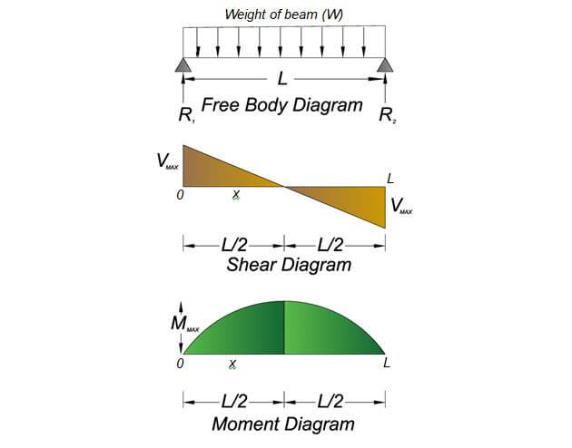
Figure 14: Simple beam with uniformed load diagrams
This diagram is typically used when a beam is supported at both ends for only the weight of the beam. The downward force is equal to the weight of the beam. The weight is evenly distributed evenly the entire length of the beam, which is why the vectors are of equal size.

There will be upward reaction forces at the support that will counteract the weight of the beam. The force at each support will be equal to one-half the entire weight.

The next figure shows the shear force diagram. The shear force acting at any point “x” on the beam is governed by the below equation. The shear force is at its maximum at the supports. You can see that when 0 and L are inserted into the equation for x, the value will be of magnitude equal to ½ the weight.


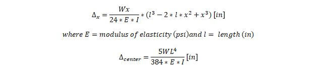
The bending moment acting at any point “x” on the beam is governed by the following equation. The moment is at its maximum at the center. The moment will be equal to zero when “x” is equal to “L” or “0”.

The deflection at any point “x” on the beam is governed by the following equation. The deflection is at its maximum at the center.
The moment can then be used to find the maximum stress in the beam. The maximum stress in the beam will help to influence the beam dimensions and material choices. The maximum stress will be discussed in the Strength of Materials section under Bending.
The information shown on this website is a sample of the material provided in the technical study guide and sample exam. See the STORE to buy the products for continuation on Economic Analysis and Basic Engineering Practice for the Mechanical Machine Design & Materials PE Exam.
First Moment of Area
The first moment of area should not be confused with the moment of inertia which will be discussed in the following section. The first moment of area is equal to the sum of the area multiplied by the distance to an axis. The axis is the centroid of the area. There are two first moments of area, one about the x-axis and the other about the y-axis for a 2-dimensional object.
The information shown on this website is a sample of the material provided in the technical study guide and sample exam. See the STORE to buy the products for continuation on Project Management and Basic Engineering Practice for the Mechanical Machine Design & Materials PE Exam.
Moment of Inertia or Second Moment of Area
Moment of inertia or second moment of area is used to convey the situation when forces act upon a three dimensional object, the internal forces within the object will vary based on the distance from the forces and the cross section of the object. For example, if. The stresses within an object will vary throughout the thickness of the object. The previous topic on beams showed the moments, based on the assumption that the object was a uniform beam.
The information shown on this website is a sample of the material provided in the technical study guide and sample exam. See the STORE to buy the products for continuation on Units & Conversions and Basic Engineering Practice for the Mechanical Machine Design & Materials PE Exam.
Dynamics
The previous topic, Statics, was focused on forces and moments on static objects. Dynamics uses the same forces, moments and free body diagrams but focuses on the effect of those concepts on moving (dynamic) objects. There are two main topics in Dynamics, (1) Kinematics and (2) Kinetics. Kinematics is concerned with the linear and angular motion of objects. Kinetics is concerned with the forces that cause the motion in kinematics.
Kinematics
Kinematics type problems will be centered on finding one of these three variables, (1) the distance traveled by an object, (2) the velocity of an object or (3) the acceleration of an object at any given time or location. If a problem asks for one of these three variables and forces are not involved, then most likely the solution will be found using the equations presented in the kinematics section.
Within the topic of kinematics you may encounter problems with either linear motion or angular motion. Linear motion is the movement of an object within the x-y-z plane in either a straight line or a curve. Curve type movement is typical of projectiles and straight line movement is typical of vehicles, sliding blocks, pistons and springs. Angular motion is the circular movement of an object about an axis, within the x-y-z plane. This type of movement is typical of gears, pumps, fans and any other equipment that rotates about an axis.
The information shown on this website is a sample of the material provided in the technical study guide and sample exam. See the STORE to buy the products for continuation on Units & Conversions and Basic Engineering Practice for the Mechanical Machine Design & Materials PE Exam.