- HOME
- FE EXAM
- PE EXAM
- DESIGN TOOLS
- COURSES
- STORE
- ABOUT
- CONSULTING
![]()
Engineering Pro Guides is your guide to passing the Mechanical & Electrical PE and FE Exams
Engineering Pro Guides provides mechanical and electrical PE and FE exam technical study guides, practice exams and much more. Contact Justin for more information.
Email: contact@engproguides.com
EXAM TOOLS
Material Properties
for the Machine Design & Materials P.E. Exam
by Justin Kauwale, P.E.
Introduction
The Material Properties section accounts for approximately 8 questions on the Machine Design & Materials Mechanical PE exam. On the NCEES outline, the Material Properties are split between Physical, Chemical and Mechanical groups of properties. The physical properties are measurable properties that describe the state of a material and do not depend on the size of the material. Physical properties also describe the behavior of a material as it changes state, like when a material is melted and the state changes from solid to liquid. The chemical properties describe how a material changes into a different material, like when a material corrodes or oxidizes. Do not confuse chemical properties with physical properties changing states. A solid or liquid material is still the same material, which describes the physical properties. The mechanical properties describe the behavior of materials under thermal or mechanical loading. The majority of the Machine Design & Materials PE exam focuses on the Mechanical Properties. However, you should still be familiar with the physical and chemical properties.
The information shown on this website is a sample of the material provided in the technical study guide and sample exam. See the STORE to purchase these items.
Physical Material Properties
During the exam you will need to be able to find and use material properties to complete many problems. You should be very familiar with your resources and where to find these material properties. As you go through these descriptions of the important material properties, look through your Mechanical Engineering Reference Manual and your Machinery Handbook. Tag the appendices that contain these properties and recognize the units. The key is to not waste time looking for material properties and to not make mistakes when solving a problem due to incorrect units.
Density
The density of a substance is its mass per unit volume, basically how heavy is something in one cubic foot or one cubic meter.
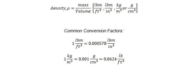
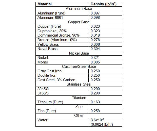
The density is typically used to calculate the overall weight of a material based on its volume. The table below lists densities of common metals. You may find that different sources have varying densities for metal alloys. Therefore, it is likely that the test will provide you with the density values when referencing an alloy to avoid possible discrepancies.
Specific volume is the inverse of density and is measures as a volume per unit mass.

Melting Point
The melting point is the temperature at which a solid will turn into a liquid at atmospheric pressure. An alloy may have two melting points, solidus and liquidus. Solidus is the temperature at which the metal turns from completely solid to a solid and liquid mixture. Liquidus is the temperature at which the metal turns from a solid and liquid mixture to completely liquid. The eutectic point is a specific composition where the metal transitions from completely solid to completely liquid.
The following figure is a phase diagram for a copper-silver alloy and depicts an example of the solidus and liquidus melting temperatures for various alloy compositions. Observe the eutectic point at approximate 28% copper. The phase diagram will be discussed more later on in this section and it is also used in the Heat Treatment topic under Section 9.0 Supportive Knowledge.
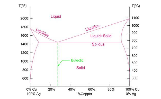
Figure 1: Phase diagram of Solidus and Liquidus Melting Points
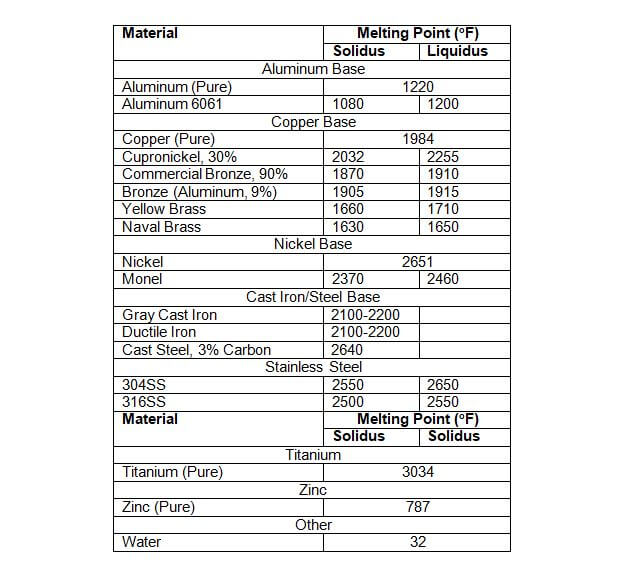
The following table list melting points for common metals. Alloys have a solidus and liquidus melting point as described above.
Optical
There are four major optical properties of a material: reflectance, transmittance, absorbance, and emissivity. When a beam of light hits a solid object, it is either reflected, transmitted or absorbed. The sum of the reflectance, transmittance, and absorption is equal to the incoming light, also known as incident light. Emissivity is how much light can be radiated by an object and is expressed as a ratio to a perfect black body.

Figure 2: Reflected, Transmitted, and Absorbed Light
Reflectance: Reflectance is the amount of light that is reflected back from the object. A mirror has high reflectivity, low transmissivity, and low absorptivity
Transmittance: Transmittance is the amount of light that goes through the material. For example, glass has a high transmittance, but low reflectivity and low absorptivity.
Absorptivity: Absorptivity is the amount of light that gets absorbed into a material. Opaque and dark objects have higher absorption. Asphalt has a high absorptivity.
Emittance: The incident light or energy that is absorbed into an object can then be emitted from it. Emissivity is how much thermal radiation in the form of light and infrared radiation is emitted from an object compared to a perfect black body. A perfect black body is an object that can absorb 100% of the incoming light, and also emit 100% of this absorbed energy.
Corrosion
One such chemical property is corrosion. Corrosion is the deterioration of a material over time. Corrosion is accelerated when exposed to hostile environments or in contact with certain materials. Being able to understand which metals are more or less susceptible to corrosion is important for selection of materials in varying machine design applications.
The corrosion rate is determined by the thickness surface deterioration over time, typically measured in mils/year, where 1 mil = 0.0254 mm or one-thousandth of an inch (.001 in)
Corrosion Rates
The corrosion rate is determined by the thickness surface deterioration over time, typically measured in mils/year, where 1 mil = 0.0254 mm or one-thousandth of an inch (.001 in)
Corrosion rates are measured by finding the weight difference of a metal over time to calculate the material loss./

Galvanic Series
The most common types of corrosion occur when metals are exposed to salt laden or acidic air. Corrosion can also be accelerated when dissimilar metals are in contact with each other. This is known as galvanic corrosion. The farther apart the materials are on the galvanic series chart, the more likely the metals are to exchange electrons between each other, causing corrosion.
The galvanic series tables rate which metals are more likely to undergo corrosion. It is measured based on a metals electric potential compared to a reference material. A metal that is anodic (a metal that loses electrons, i.e. negative voltage potential) is more vulnerable to corrosion, while a cathodic material (the metal that receives electrons, i.e. positive voltage potential) is more stable and is better at resisting corrosion. For example, steel and cast iron will corrode faster than titanium and stainless steel. Furthermore, 316 stainless steel resists corrosion better than 304 stainless steel.
Figure 3: Galvanic Series in Salt Water Chart
Corrosion Protection
Sometimes it is not feasible or cost effective to select a material that is resistant to the corrosive agents of your application. For example, a certain material strength is required and cannot be sacrificed by replacing one type of metal for another or an inert metal is much too costly for your project. If this is the case, then you must pursue other options of corrosion protection. Some of these methods are shown in the next few paragraphs.
Paints & Coatings
For metals exposed to harsh environments, paints or coatings can be applied. Common coating types include epoxy, phenolic, zinc, and polyurethane. The specific types of coatings are beyond the scope of this book. The application and testing methods for coatings are governed by ASTM, the National Association of Corrosion Engineers Standards (NACE), and the Society for Protective Coatings (SSPC).
Isolation Kits/Dielectric Unions
Galvanic corrosion between dissimilar metals is prevented by the following methods: (1) using metals that are similar in electrode potential on the galvanic series chart, (2) coatings, and (3) dielectric unions or isolation kits.
Isolation kits use gaskets and sleeves to isolate one metal from the other and prevent the electrode transfer that causes the galvanic corrosion.
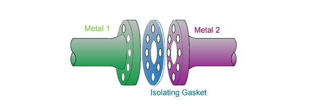
Figure 4: An isolation kit uses a non-conductive gasket to stop the electrochemical reaction.
Dielectric Unions act in a similar manner. A dielectric union is a fitting with two different metals on opposite ends and an internal material that isolates the dissimilar metals from each other.

Figure 5: A dielectric union separates two connected pipes of dissimilar metals with a non-conductive washer shown in blue. Normally an electrochemically reaction will occur from the more noble metal to the less noble metal with the water serving as the path connecting the two metals. The dielectric union stops this reaction by physically separating the metals.
Cathodic Protection
Cathodic protection uses a sacrificial anode that has a more negative electrode potential than the metal it is protecting. The two metals are connected, typically by a wire, and ultimately the corrosion occurs at the sacrificial anode and not the protected metal. Typical sacrificial anode materials are zinc, aluminum, or magnesium.
Another method of cathodic protection is by galvanization. In this process, a metal is coated with zinc, typically by hot dip galvanizing, which submerges the metal into liquefied zinc. The protective coating then acts as the sacrificial anode to the metal beneath it. Even if part of the metal is exposed, the zinc will still act as the anode and protect the adjacent metal. It is important to note that galvanization does not protect against acidic corrosion.
For additional information on corrosion, the NACE Corrosion Engineer’s Reference Book provides a compilation of data, tables, and charts of various corrosion types, causes, and protection methods. It is more technical than required for the test, but provides a comprehensive reference of supportive data for corrosion engineers.
Oxidation
The corrosion of metals does not always require a liquid to promote the electrochemical reaction. Oxidation is the act of corrosion in gas and for the purposes of the exam the gas will be air. It will be difficult to test this topic numerically, but you should be familiar with the overall concept of oxidation and chemically how oxidation occurs.
A metal with two electrons (divalent) will be combined with ½ oxygen molecule to form a metal-oxide.
If the metal has more electrons, then the same ratio will be used to complete the above reaction. For example, the following shows the reaction for aluminum.

Aluminum has 3 electrons, thus the least common multiple is 6 electrons, which requires 2 aluminum molecules and 3 oxygen molecules. Mor examples of the oxidation reacton are shown in the table below.
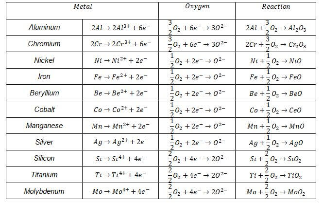
The following figure shows how a metal oxide film forms on the surface of a metal with 2 electrons.

Figure 6: Oxidation occurs when electrons flow from the metal to the air. This causes a film to form on the top layer of the metal. This film is a metal-oxide.
Alloys
Alloys are created to produce a material with improved characteristics for a specific application. Alloys consist of a mixture of metals and sometimes employ other elements. A common PE problem will be to determine the correct alloy for a desired requirement, like meeting a physical or chemical requirement, such as strength or corrosion resistance. Since steel alloys are the most common in the Machine Design & Materials field, you will most likely have a question on steel alloys with respect to their differing material properties.
Steel Alloys
Steel was created by combining iron, carbon, and other elements to create a strong, economical material. By varying the composition of metals, various types of steels with different hardness, toughness, corrosion resistance, and strength are produced.
For the PE exam you should understand the AISI/SAE steel coding system. The last two or three digits (right side) stand for the carbon content in 1/100%. Thus, 1040 steel has a carbon content of 40/100% or 0.40% carbon. The first two digits represent the allow category. There are many different categories but the main ones are 10_ _, where 10 represent plain carbon steel.
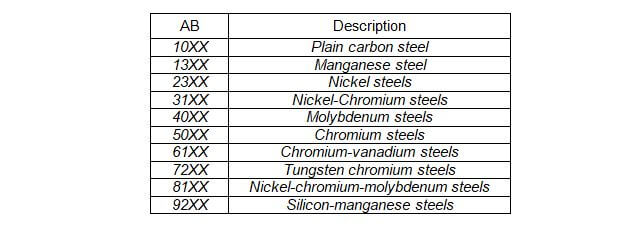
The second two digits represent the amount of carbon present in the steel.

Stainless steels are represented differently. Stainless steels are alloys of iron and chromium. Stainless steels have a minimum Chromium weight percentage of 10.5%.
AISI stands for American Iron and Steel Institute and SAE stands for the Society of Automotive Engineers.
You should find the material properties for the steel alloys in your references and tab this location for the PE exam.
Phase Diagram
A basic skill that you should know for the PE exam is how to read phase diagrams. A phase diagram graphically represents the state of a material at varying conditions (i.e. temperature, pressure, composition, etc). For machine design, the most relevant type of phase diagram is the binary phase diagram. Binary phase diagrams are used to identify the properties of an alloy based on the temperature and composition of the material. The image below is an example of the simplest phase diagrams: Copper-Nickel.
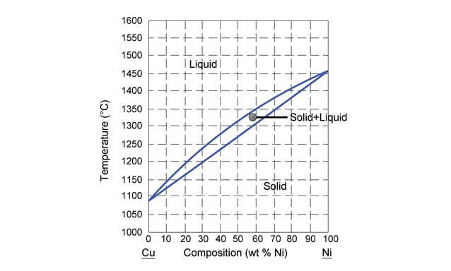
Figure 7: Copper nickel phase diagram
Coordinates: The graph plots the composition of two different metals, in this case the percentage of copper and the percentage of nickel, along the x-axis, against the temperature on the y-axis.
Boundary Line: Each line represents the boundary around a phase region.
Phase: Within each boundary is a unique phase of the metal. In this case, there are only three phases: liquid, solids, and a center region where both solid and liquid exist.
Reading a Phase Diagram
Typically in manufacturing, the composition of an alloy is known (i.e. the x-axis is known) and you want to know how the alloy will change with temperature and will move vertically along the graph. Assume you have an alloy comprised of 60% nickel, melted to 2600oF. Locate this point, A, on the graph. Following this point down vertically, you can see that the solid + liquid region begins at approximately 1350 oC and the alloy will transition to completely solid at approximately1300 oC.
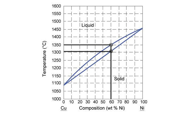
Figure 8: This figure shows the solid and liquid temperatures for a 60% nickel composition in a copper-nickel alloy.
Lever Rule
The solid + liquid region contains a mixture of solid and liquid components. Assume you are located at a point “x” inside of this region, with coordinates, “Cx, Tx”. The percentage of solid and the percentage of liquid can be determined with the lever rule. Conceptually you can see that the point is closer to the liquid region (left). Therefore, there will be more liquid components than solid components in the mixture.
To use the lever rule, draw a horizontal line through the point B, extending from one boundary line to the other. This is known as the tie line. Find the composition at each intersection point of the boundary line and at point “x”. The composition shall either be in terms of Nickel or Copper, this does not matter; it just matters that you are consistent.
Finally calculate the percent weight of the liquid and solid.

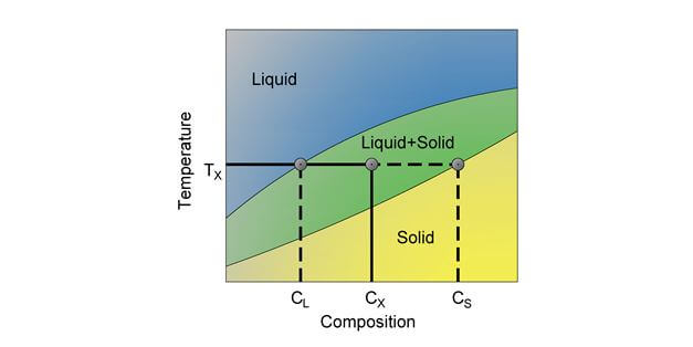
Figure 9: In the above figure the point Cx, Tx is comprised of both solid and liquid. The percentage of solid and liquid can be found by using the lever rule.
Iron Carbide Diagram
The most important binary phase diagram is the Iron-Carbide diagram, since this diagram represents the phases for the most common metals in manufacturing: steel and cast iron. The iron carbide diagram describes the alloy material based on the percent carbon (C) and iron (Fe) in the alloy. The temperature of the material will also affect the alloy material.
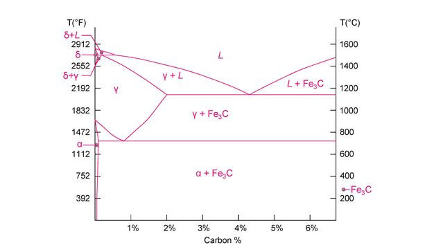
Figure 10: The above diagram shows the various phases and mixed regions as a function of the % carbon and temperature of the Carbon-Iron mixture.
The following table will define each area of the phase diagram.
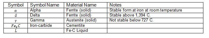
Between the major phases are the mixed regions. In the mixed regions you must use the lever rule to find the percentage of ferrite, austenite (alpha or delta), cementite or liquid. In addition, each of the mixed regions has special names as shown in the following figure. However, you should not need to know each definition for the PE exam, since it would be very detailed.
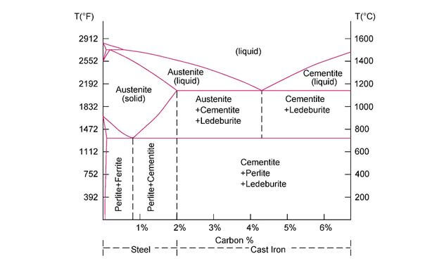
Figure 11: Sample Iron-Carbide diagram
The graph above appears to show only two classifications of alloys, Cast Iron and Steel. Cast iron is classified as Iron-Carbon mixtures with around 2 to 7% carbon (the remaining percentage is iron). Steel is classified as having a carbon percentage between .01% to around 2%, with the remaining percentage as iron. There is a third classification at less than .01% carbon and it is simply iron, since nearly 100% of the alloy is iron.
Mechanical
The mechanical properties of materials are found by a series of tests. These tests include the tension or compression test, which determines the Stress-Strain diagram. The Rockwell or Brinnell tests determine the hardness of the material. There are also many more tests that determine the other properties like creep, thermal expansion, thermal conductive, specific ehat capacity and visco-elasticity. Each of the mechanical material properties will be discussed in the next paragraphs.
Stress-Strain Diagram
The tension and compression tests determine the strain at various stress levels. This results in the stress-strain diagram. A sample of the stress strain diagram is shown below.
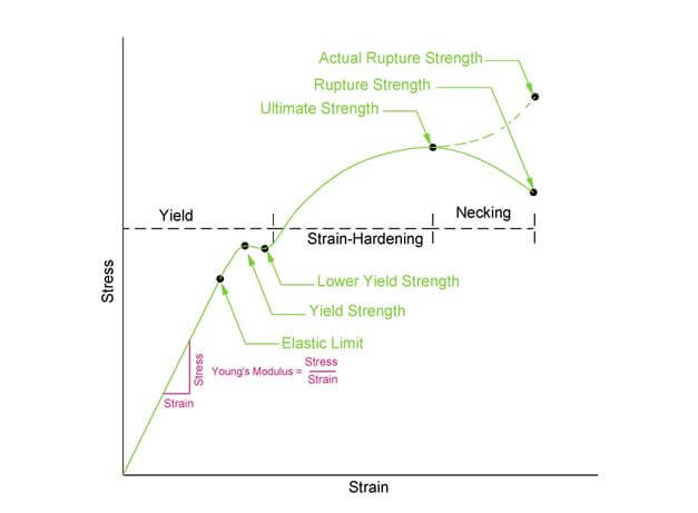
Figure 15: This graph shows the various material properties for a ductile material.
The information shown on this website is a sample of the material provided in the technical study guide and sample exam. See the STORE to buy the products for continuation on Economic Analysis and Basic Engineering Practice for the Mechanical Machine Design & Materials PE Exam.
Hardness
Hardness is the property that describes a material’s ability to withstand abrasion, scratching and indentation. Hardness is measured in terms of MPa or is a dimensionless value. The hardness measurements are useful when comparing one material to another.
Hardness is measured by any one of the following tests, (1) Rockwell, (2) Brinell, (3) Meyer, (4) Vickers, (5) Knoop or (6) Scleroscope. Each of these tests use a different object of varying shape and material to impact the subject material. The effect of this impact due to a known force is then measured and a hardness value is assigned. The two main tests that you should know for the PE exam are Rockwell and Brinell. You should also know that hardness values are not absolute, these tested values are relative to each other. Hardness values are used to compare the hardness between different materials.
Figure 16: Hardness tests involve a known load impacting a material’s surface and the measurement of the load and the result of the impact upon the material’s surface.
The information shown on this website is a sample of the material provided in the technical study guide and sample exam. See the STORE to buy the products for continuation on Rockwell, Brinell and References for Hardness for the Mechanical Machine Design & Materials PE Exam.
Creep
The term creep strength, describes a materials ability to withstand a constant load. This term is similar to the fatigue term in the Strength of Materials section. Fatigue is concerned with repeating, on-off loads, while creep is concerned with steady, always on load. Creep strength is the stress level at which a material will fail at a certain time and certain temperature. This stress is typically less than the yield strength of the material. This is why it is important to understand creep when selecting a material to ensure that your design takes into account the long term effects of creep. You may select a material that meets the yield strength for the current design situation, but over time creep will occur and the material may fail. In practice, creep is taken into account by assigning a safety factor to the yield strength and in more sensitive situations, your design should include the lifetime of the material and the creep strength.
Creep strength is defined as the stress that will result in a certain value of elongation at certain time and temperature. Creep tests are conducted on the materials where a constant stress is applied at a certain temperature and the strain is measured over time.
The information shown on this website is a sample of the material provided in the technical study guide and sample exam. See the STORE to buy the products for continuation on Creep for the Mechanical Machine Design & Materials PE Exam.
Thermal Expansion
When heat is added to most materials, the average amplitude of the atoms' vibrating within the material increases. This, in turn, increases the separation between the atoms causing the material to expand. If the material does not go through a phase change, the expansion can be easily related to the temperature change. The linear coefficient of thermal expansion (α) describes the relative change in length of a material per degree temperature change. As shown in the following equation, α is the ratio of change in length (∆l) to the total starting length (li) and change in temperature (∆T).
When a pipe is heated or cooled, the length of the pipe will change based on the temperature and a coefficient of thermal expansion which is dependent on the material.
The information shown on this website is a sample of the material provided in the technical study guide and sample exam. See the STORE to buy the products for continuation on Thermal Expansion for the Mechanical Machine Design & Materials PE Exam.
Thermal Conductivity
Thermal conductivity is the ability of a material to conduct heat with a given temperature difference. Thermal conductivity is the material property that measures the rate of change in heat per unit distance per unit temperature difference.
More commonly on the PE exam you will use the following equation to conduct an energy balance as energy is transferred from one material to another material. The first step is to find the heat flow rate through an area of the subject material, as shown below.
The information shown on this website is a sample of the material provided in the technical study guide and sample exam. See the STORE to buy the products for continuation on Thermal Conductivity for the Mechanical Machine Design & Materials PE Exam.
Specific Heat Capacity
The specific heat describes the ease of a fluid or solid to increase in temperature when heat is applied. Specific heat is also known as heat capacitance and can be thought of as an object’s ability to hold and gain heat. For solids and liquids, specific heat is shown as the variable, cp.
Water has a specific heat of 1.0 (Btu/(lbm F)), while aluminum has a specific heat of 0.23 (Btu/(lbm F)). As heat is added to water, water will increase in temperature at a slow rate. Since aluminum has a lower specific heat, it needs less energy to raise its temperature.
The information shown on this website is a sample of the material provided in the technical study guide and sample exam. See the STORE to buy the products for continuation on Specific Heat Capacity for the Mechanical Machine Design & Materials PE Exam.
Visco-Elasticity
The term visco-elasticity describes a material’s ability to undergo strain under an applied load and then return back to the material’s original shape after the load is removed. This material property is tested with the stress-relaxation test. In this test, a strain is quickly applied to a material and the stress is measured over time to maintain that strain. A visco-elastic material will require a nearly constant level of stress over time to maintain that strain. A viscous material will require less stress over time because the material will begin to “relax” and will slowly reduce the strength of the bonds within the material.
The information shown on this website is a sample of the material provided in the technical study guide and sample exam. See the STORE to buy the products for continuation on Visco-Elasticity for the Mechanical Machine Design & Materials PE Exam.