- HOME
- FE EXAM
- PE EXAM
- DESIGN TOOLS
- COURSES
- STORE
- ABOUT
- CONSULTING
![]()
Engineering Pro Guides is your guide to passing the Mechanical & Electrical PE and FE Exams
Engineering Pro Guides provides mechanical and electrical PE and FE exam technical study guides, practice exams and much more. Contact Justin for more information.
Email: contact@engproguides.com
EXAM TOOLS
Mechanical Components for the
Machine Design & Materials P.E. Exam
by Justin Kauwale, P.E.
Introduction
Mechanical components accounts for approximately 18 questions on the Machine Design & Materials Mechanical PE exam. The Mechanical Components section is the largest section on the Machine Design & Materials PE exam. This section has 18 questions according to the NCEES outline. There are also 13 sub-topics, which is a huge indicator of what will be on the PE exam. The 13 sub-topics means that there can only be 1 or 2 questions on each sub-topic, thus the type of questions on each sub-topic must be very focused on the most commonly, encountered design questions within that sub-topic. In order to highlight the importance, you should notice the difference between the Engineering Science and Mechanicals section which has 10 questions and only three sub-topics. This means that there are 3 or 4 questions on each sub-topic, so the questions can include the most commonly encountered questions and even some less commonly encountered questions.
In this section, each sub-topic is focused on a specific mechanical component. Each component will include the most commonly encountered design equations and some background information on each component. The purpose of this section is to provide you enough background information on each component, so that you are able to use the equations on each component with confidence. On the PE exam, you will encounter questions on a specific component and there will be extraneous information like terms and values. You should be familiar with the terms, confident in using an equation and secure when leaving out extraneous values from an equation.
All the components that are listed on the next page are all related to one another. Shafts and keys are used alongside with clutches and brakes. Pressure vessels hold hydraulic and pneumatic fluids. Hydraulic and pneumatic fluids are used to actuate clutches and brakes. Belts, pulleys, gears and chain drives are used to drive shafts. Springs and dampers are used to minimize vibrations. Mechanisms can be used to translate rotational motion into linear motion to drive actuators. Power screws can use rotational motion to cause linear motion. Motors and engines are used to provide the power to drive rotational motion, which is used throughout all the components. You should be familiar with how these components can be used together, because on the PE exam you may encounter problems that use multiple components together.
The information shown on this website is a sample of the material provided in the technical study guide and sample exam. See the STORE to purchase these items.
Pressure Vessels
A pressure vessel is a container designed to hold gases or liquids at a pressure substantially higher than ambient pressure. In Machine Design, pressure vessels are used to hold compressed air or hydraulic fluid.
Pressure vessels are used to store both gases and liquids. Pressure vessels can come in a mixture of spherical and cylindrical shapes and these vessels can have thick or thin walls. The primary pressure vessels that you should know are the thin wall pressure vessels, but thick wall pressure vessels are also on the NCEES Machine Design outline.
Typical questions on the PE exam may include finding stresses or designing pressure relief valves. The stresses within the pressure vessel can be one of three types, (1) hoop stress, (2) longitudinal stress or (3) radial stress.
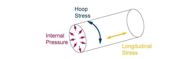
Figure 1: A pressure vessel will experience internal pressure due to the compressed fluid. This will result in stresses in the material in both the longitudinal direction and also in the tangential direction.
(1) Hoop Stress: Hoop stress can also be called tangential stress. This is the stress that is tangent to the surface of the pressure vessel.
(2) Longitudinal Stress: The longitudinal stress is sometimes called axial stress. This stress is parallel with the axis of the pressure vessel. This stress creates tension in the longitudinal direction.
(3) Radial Stress: Radial stress is the stress that pushes perpendicular against the surface of the pressure vessel from the inside. This would be equivalent to the internal pressure of the liquid or gas within the pressure vessel.
Thin vs. Thick Wall
The thin walled pressure vessels make calculations easier. A thin walled pressure vessel is defined as having a ratio of radius to thickness as greater than 10.


A thin walled pressure vessel uses membrane theory, which assumes that the hoop stress in the thickness of the wall does not vary. The hoop stress within the thickness of the wall is constant from the outside of the wall to the inside of the wall.
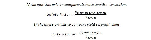
Design Factor
A design factor is a factor of safety that is applied to the design of the pressure vessel. In engineering practice, you do not design a pressure vessel at its design pressure, you typically provide a factor of safety to ensure that the pressure vessel is designed to withstand much more than the expected stresses in the pressure vessel.
Materials
The pressure vessel stresses should be designed well below the maximum allowable stresses of the pressure vessel material. For the exam, you should have the following material properties readily available.
- Ultimate tensile strength or tensile strength: The maximum stress before failure.
- Yield strength: The maximum stress before permanent deformation occurs.
Spherical vs. Cylindrical
The two main pressure vessel shapes in Machine Design are spherical and cylindrical. The hoop stress for these pressure vessels will be dependent on the internal pressure (assuming no external pressure), radius and thickness. These equations only work if the pressure vessel qualifies as a thin walled pressure vessel.

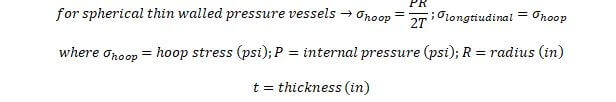
The hoop stress is typically the design criteria for pressure vessels, since this stress is much higher than the internal pressure and is twice the longitudinal stress for cylindrical pressure vessels. The hoop stress and the longitudinal stress are equal to one another because stresses are the same in all direction for spheres. There is no longitudinal axis in a sphere.
Thick Wall Theory
If you encounter a thick wall pressure vessel, then you cannot use the previous equations. You must use the following Thick Wall Theory equations. These equations show that the stress in the thickness of the wall of the pressure vessel will vary based on the location that stress is measured within the wall thickness.
The hoop stress and radial stress will vary based on location “r”.
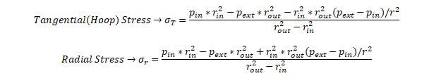
The sum of the hoop stress and the tangential stress will be constant and independent of location “r”.

The longitudinal stress is also independent of location “r”.
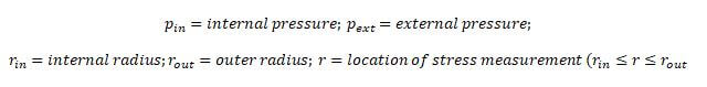
When there is only internal pressure then the critical condition will occur when location “r” is equal to the internal radius of the pressure vessel. If you substitute the external pressure as zero, then the hoop stress equation reduces to the following.
In Machine Design, typically pressure vessels are only subject to internal pressures. However, you should be able to deduce the equations for external pressure only with the critical condition occurring at the outer radius.
Bearings
Bearings are used to separate two components, while permitting relative motion between the two components. Bearings are designed to have very little friction and often have a lubricant between the bearing and the components.
There are two main types of bearings, plain surface bearings and rolling contact bearings. A rolling contact bearing consists of either a ball or roller between the two components. A plain surface or sliding bearing or journal bearing consists of a bearing surface and no rolling elements. This is common of a shaft rotating within a bushing. This is a housing that sits around a shaft that provides a bearing surface. The PE exam will most likely focus on the rolling contact bearings and the lubrication of plain surface bearings. Each type of bearing has sub-types as shown in the figure below.
In the Machine Design field, the two types of bearings each have their own typical design questions that can occur on the PE exam. For roller contact bearings, typical questions focus on the load and life of the bearing. In application, you will encounter bearings that have a rated load and rated life. You will have to interpret this information and apply it to your situation. This typical process will be discussed in the life-load analysis.
For plain surface bearings, you must analyze the lubricant that is used. You must determine the appropriate lubricant based on viscosity, temperature and you must also determine the amount of clearance between the two components. This will be discussed in Lubrication Analysis.
Lubrication Analysis
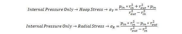
Lubrication analysis is based on finding the correct type of lubrication, viscosity, temperature and amount to properly suit the design of the plain bearing or journal bearing. This analysis is not normally used for roller-contact bearings. The most common type of lubrication is called boundary lubrication. In this type, the lubrication provides a microscopic thin layer between the two moving components. The following bearing characteristic number also known as the Sommerfeld number is a dimensionless number that is used in selecting the properties of the lubricant.
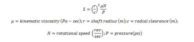
The radial clearance is the clearance between the shaft and the bushing. The pressure is the force per area that the shaft imparts on the lubricant. Since the shaft is cylindrical, the pressure can be found through the following equation, where r is the radius of the shaft and L is the length of the shaft.

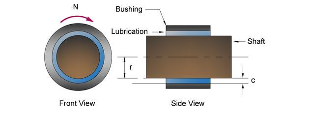
Figure 2: The bearing characteristic number is based on the radius of the shaft, the clearance between the shaft and the bushing, the viscosity of the lubrication fluid, the rotational speed of the shaft and the pressure of the shaft on the lubricant.
The Sommerfeld number is mostly determined by the shaft speed (N), shaft weight (W), shaft dimensions (D, L) and the shaft fit (c). In lubrication analysis, you must select the appropriate lubricant, which will determine the viscosity value. The SAE and lubrication manufacturers publish lubricant graphs that look like the one below. These graphs show the relationship between viscosity and temperature. As the temperature increases, the viscosity decreases. When selecting a lubricant you should pay attention to its operating temperature and choose one of sufficient viscosity for the applicable operating temperature.
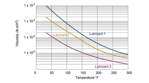
Figure 3: The viscosity of a lubricant will decrease as temperature increases.
Once you have selected the lubricant and found the viscosity that corresponds to the operating temperature, then you can determine the Sommerfeld number. This number and the L/d ratio of the shaft will then determine the minimum film thickness through graphs that look like the next figure.
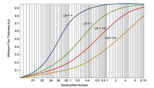
Figure 4: Once you have found the Sommerfeld number then you can use a similar graph to find the minimum film thickness.
The term h0 is the minimum film thickness and c is the clearance that was previously determined by the shaft fit. The minimum film thickness is typically designed to be greater than the roughness. If the surface roughness of the components is greater than the minimum film thickness of the lubricant, then the lubricant will not protect the surface of the components and the components will degrade. If you do not have adequate minimum film thickness then you may have to select a different lubricant with a greater viscosity, however there is a tradeoff between the viscosity and the amount of friction that is created by the lubrication. These two opposing qualities of a lubricant make the process of selecting a lubricant difficult. However, for the purposes of the exam you should just be familiar with the steps in this process. It is most likely that a question in this area will only focus on one step, since there is only 6 minutes available to complete a problem.
Life Load Analysis
The life load analysis topic under the NCEES outline primarily refers to roller contact bearings, since these bearings will fail due to fatigue and their life is dependent on the load. The basic equation that you must use for life-load analysis type questions for ball bearings is as shown below. The life of a ball bearing varies by the cubed of the load. This means that if the load on a ball bearing is doubled, then the life of the ball bearing compared to the original life is cut by 1/8th.

Roller bearings have a different ratio from ball bearings. These roller bearings are cylindrical or needle type bearings.
Roller contact bearing manufacturers provide data for the load, rating life, life, median life, basic load rating, etc. The rating life is the life at which 10% of bearings have failed and is shown as the variable, L10. Life is determined as the number of revolutions the roller bearing can withstand prior to showing signs of fatigue. The median life is the life at which 50% of the bearing have failed and is shown as the variable, L50. These life values are given as a function of the rated load, C. If your actual load is different from the rated load, then you must use the previous equations to find the actual life of the roller bearing under your actual load.
It is important to note that the load shown is the dynamic load. This means that the bearings are rotating and there is not static concentrated load on the bearings. If the bearing is not moving, then there will be a static concentrated load on the bearing. The bearing must be strong enough to withstand this load. The capacity given by manufacturers is shown as the variable, Pst. This is the maximum load that the bearing can withstand when at rest. If this value is exceeded then the bearing will be indented and would lead to the failure of the bearing through crack propagation.
Gears
Gears are used to transmit rotational energy from one shaft to another shaft. Gears can also be used to adjust the speed to match a certain requirement. For the purposes of the PE exam you should have a basic understanding of the construction of gears, the different types of gears, how speeds can be changed with gear ratios and the forces present in a gear.
Gear ratios are defined as the ratio of teeth, N, between two mated gears. The number of teeth for gears can be used since the spacing between the teeth is the same, in order for the gears to properly mate.

The most fundamental concepts for gears is understanding that the relationship between the rotational speeds, n, of two gears is the inverse of the quantity of teeth, N, in each gear and that the ratio of torque, T, is the inverse of the rotational speeds.

Typically the gear ratio is given in terms of the driven over the driving or the output over the input gear. In the previous equations, n1 is the driven gear speed and n2 is the driving gear speed.
The technical study guide contains the following topics on gears, spur gears, helical, bevel, worm, pitch circle, circular pitch, diametral pitch, helical gear pitch, tooth thickness, speed analysis, force analysis and more.
Springs
The topic of springs was initially discussed in Section 6.0 Vibration, but it is reintroduced in the section with an emphasis on applications. A spring provides an opposing force that is dependent on the stiffness of the spring and the deflection of the spring from its free length.
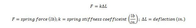
If the spring is not deflected then it is at its free length. The spring force at a deflection of 0 will be equal to zero. When a spring is deflected at a design or operating load, then the force will be found using the previous equation. If the spring is fully deflected, then it is at its maximum load. This full deflection amount is often called solid length.
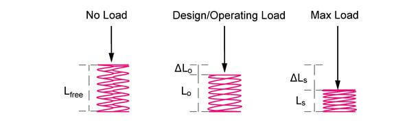
Figure 5: A spring's force is corresponds to the level of deflection.
The springs topic continues in the technical study guide with different types of springs, force analysis and fatigue analysis.
Dampers
Dampers was covered heavily in Section 6.0 Vibration, along with springs. The types of damper questions in that section dealt with natural frequencies, damped frequencies and forced frequencies. This section on dampers mostly deals with energy dissipation through damping. However, on the NCEES outline under Mechanical Components, it reads, “Dampers (e.g., types, selection). This most likely hints at questions that revolve around the most common types of dampers and how to select these dampers.
Damping are devices that are used to reduce the vibration in a mechanical system by causing the vibration to be released as heat. The damper accomplishes this feat through friction either dry friction, solid friction or viscous friction. These dampers can also be called shock absorbers. A good source of information on dampers is to look at the manufacturer’s websites. This website has a bunch of dampers and good descriptions that will help you to become even more familiar with dampers.
Link: Enidine Products
Link: Enidine Shock Absorbers and Rate Controls (Energy Absorption Theory and Selection Process)
The second link provides information on some theory, how to size shock absorbers and also how to select shock absorbers. The technical study guide has more information on some selection process and energy equations.
Belt, Pulley and Chain Drives
Belts, pulleys and chain drives are typically used to connect to motors. The power and rotational speed is determined by the purpose of the machine like a conveyor belt that needs to carry a certain amount of weight at a certain speed. Once, the power and rotational speed are determined, the belts, pulleys and/or chain drives can be designed to communicate this speed and power from the motor (source) to the need. As you go through this topic, remember to keep the equations in relation to horsepower and speed.
Belt Drive
Belt drives are important, because belt drives are able to deliver varying torques by varying the rotational speed of the belt. Belt drives transmit power from one rotating shaft to another rotating shaft. There are efficiency losses but these typically range to around 5 %. The total power transmitted is calculated based on the speed of the belt and the difference in tension from the tight side to the loose side.

In the machine design field, the belt must be designed to withstand the speed, tension and ultimately the stress due to tension. Power can also be found based on the following equations for torque that is applied on the pulley.


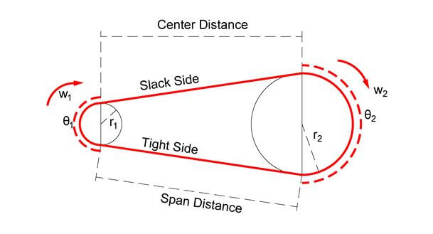
Figure 6: This figure shows the variables for belt drives that will help you to solve the following equations.
The angle of wrap is given as theta 1 and theta 2. These angles are important because they determine the amount of the belt that is in contact with the pulley.

The amount of torque on each of the pulleys can be found with the below equations. Torque is a function of the difference in tensions between the tight and slack side and the radius of the pulley. The larger pulley will have a larger torque and a larger difference between the tight and slack side will have a larger torque.

The ratio of the tight and slack forces is equal to the natural logarithm of the angle of wrap and the coefficient of friction.

Belt drive questions can also revolve around the speed of the two pulleys. The ratio of the speeds of the two pulleys or sheaves is inversely proportional to their diameters.

When you multiply the radius (one-half diameter) by the rotational speed, the result is the linear speed of the pitch line. You can visualize this if you were to imagine a single point moving along the belt. The linear speed of this single point, also known as linear pitch speed, is shown below.

The above equation only works if the rotational speed is in radians per time. If the rotational speed is given in RPM, then RPM must first be converted to radians per minute.

The technical study guide continues with similar discussions on V-belt drives and chain drives.
Clutches & Brakes
Clutches and brakes are important in Machine Design because machines require speed control. Clutches and brakes both change the speed of rotating objects.
A clutch is designed to be able to connect and disconnect two rotating objects moving at different speeds. Once the clutch connects the two rotating objects, the two objects will either be moving at the same speed or at different speeds. If the objects are moving at different speeds, then the system is considered to be slipping and if the objects are moving at the same speeds, then the system is engaged. If the clutch is not connecting the two objects, then the system is disengaged.
Brakes are designed to slow a rotating object either to a slower speed or rest. Both the clutch and brake connect a rotating object to another object. The difference between a brake and a clutch is that a clutch connects the rotating object to another rotating object, moving at different speeds. But a brake connects the rotating object to a fixed object.
Typical problems on clutches and brakes centers on the torque capacity. The torque capacity is a function of the power of the rotating object and the speed of the rotating object, as shown in the equation below.
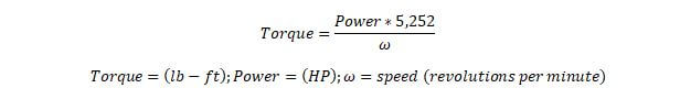
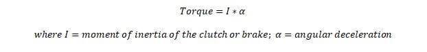
The torque can also be used to find the deceleration of a brake based on Newton’s second law of rotation.
The technical study guide continues with more information on calculating the frictional forces and torques for different types of clutches/brakes like plate type, disc type and cone type. Also included is a brief discussion on different types of actuation like Mechanical, Pneumatic and Hydraulic.
Power Screws
The purpose of a power screw is to convert rotary motion to linear motion. The simplest example is a metal screw and a nut. When installing the metal screw into a nut, you must rotate the screw in order to cause the screw to move linearly past the nut. The threading on the screw causes it to move downward or upward based on whether or not the rotation is clockwise or counter-clockwise. In this example, the screw is moved and the nut is at rest, but the opposite can also be true. The screw can be at rest and the nut can move up and down the screw.
In Machine Design, power screws are used to exert large directional forces, like with presses and to lock objects in place, like with C-clamps. Power screws are able to translate rotational force from motors to exert a large directional force.

Figure 7: A C-clammp is an example of a power screw
The technical study guide continues with discussions on the different types (acme, square and buttress) of power screws. Also included are equations for calculating lifting and lowering torque for these different types of power screws. Finally, this section ends with locking conditions and power/efficiency equations.
Shafts & Keys
The topic of shafts and keys focuses on the key, which is a component that is used to connect one rotating component to a shaft. When the key is not inserted, then the rotating components will not be connected. When the key is inserted, then the rotating components will be connected. During this time there will be stresses that will occur within the key. Problems on the PE exam will primarily be on the calculation of these stresses.
There are several types of keys, but the figure below shows the main types of keys. These keys are named after their shapes.
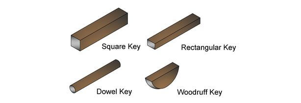
Figure 8: This figure shows different key types.
The different geometry of the keys will cause different stresses to occur within the key. There are two forces that act upon the key, (1) Torsion and (2) Compression. The torsion forces cause a key to shear and the compressive forces cause the key to bend.
The technical study guide covers the shearing forces due to torsion and the compressive forces due to bending. Also included in the guide is a discussion on stress risers aka stress concentration factors and fatigue failure.
Mechanisms
The mechanisms topic on the NCEES outline includes linkages, cams, slider cranks and levers. The NCEES outline then includes the terms force analysis and kinetic analysis. This means that in the Mechanisms topic you will need to answer questions relating to forces and movement. A cam is a rotating component that translates its rotational motion into linear motion. A linkage or a multitude of linkages connect the cam to another component. A slider mechanism directs linear motion along a specific path.
The main concept that you need to know for the force and motion analysis under mechanisms is the lever rule. A lever is a linkage connected to a pivot point or fulcrum. On the PE exam, it is safe to assume that there is no friction at the pivot point. The power into the lever equals the power output by the lever. This results in the following equation that relates the forces on either side of the lever.

The input force on one side multiplied by the distance between the applied force and the fulcrum is equal to the output force on the other side at a distance to the fulcrum. For example, if a force of 100 pounds is applied at a distance of 10 feet from the fulcrum and the output force measured at a distance of 2 feet from the fulcrum, then the measured output force will be 500 pounds.

The motion analysis for mechanisms is best learned by doing example problems. Unfortunately there is no simple concept or key for these types of problems. Each mechanism motion problem involves logic and a good handle on geometry. Please see the link below for a few easy worked examples on mechanisms. There are also practice problems at the end of this document that can also help you to gain more confidence in doing these types of problems. If you are short on time, then you should focus on other aspects of the exam, since there will only be 1 or 2 questions on this topic.
Tutorial Mechanisms – Kinematics Velocity and Acceleration DiagramsMechatronics
Mechatronics is the combination of electronics and mechanical engineering. In the machine design field this includes the interfaces, sensors, circuits, power and motors. On the PE exam, the easiest skills and concepts to test in this section are in the topics, circuits and motors. The interfaces, sensors and controls are not covered in this book, since it is highly unlikely that these topics will be tested.
Mechanical and electrical engineers work closely together and there is often a lot of coordination between the two disciplines. Most of the equipment that a Machine Design & Materials engineer designs will require power. It is important for the mechanical engineer to understand the basics of electrical engineering.
The technical study guide covers basic circuit information like resistors in parallel and series, D/C vs A/C power and ohm's law.
Hydraulic and Pneumatic Components
Hydraulics includes the equipment necessary to do work with liquid. This includes pumps, pipes, pressure vessels, control valves, actuators and connections, as shown in the simple hydraulic system below.
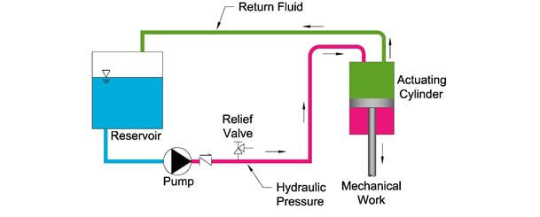
Figure 9: A simple hydraulic system consists of a reservoir that holds the hydraulic fluid, followed by a pump that pressurizes the fluid. The pressurized fluid in pink is then used to power an actuating cylinder to conduct mechanical work. In order to avoid over pressurization, there is a relief valve in the system. The green line shows the hydraulic fluid returning back to the reservoir when not needed.
Pneumatics includes the equipment necessary to do work with air. This includes compressors, tubing, pressure vessels, control valves, actuators and connections, as shown in the simply pneumatic system.
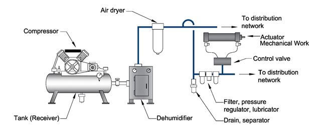
Figure 10: A simple pneumatic system consists of a receiver that holds the compressed gas, followed by a compressor that pressurizes the gas. The pressurized gas then goes through a dehumidifier, air dryer filters and drains, before it finally reaches the actuator. The actuator is used to conduct mechanical work.
The technical study guide covers pumps, dynamic head, net positive suction head, affinity laws, compressor work, actuator cylinder force, cylinder pressure, bulk modulus and hydraulic fluid flow. There is also information on control valuves used in hydrualics and pneumatics.
Motors & Engines
Motors and engines are used to transform electricity to mechanical power. A typical PE exam problem would be to size a motor or engine to provide enough mechanical power or horsepower for an actuator, a compressor, a pump, shaft rotation, power screw torque, etc. The typical PE exam skill for motors and engines is being able to convert mechanical power to electricity.
When selecting mechanical equipment, the mechanical engineer must coordinate the power requirements with the electrical engineer. This is done through the following four steps: (1) Determine Mechanical Horsepower, (2) Determine Fan/Pump Brake horsepower, (3) Determine Motor Horsepower and finally (4) Determine Electrical Power.
The technical study guide takes you through this process with examples and diagrams.