![]()
Engineering Pro Guides is your guide to passing the Mechanical & Electrical PE and FE Exams
Engineering Pro Guides provides mechanical and electrical PE and FE exam technical study guides, practice exams and much more. Contact Justin for more information.
Email: contact@engproguides.com
EXAM TOOLS
Strength of Materials
for the Machine Design & Materials P.E. Exam
Introduction
The Strength of Materials section accounts for approximately 10 questions on the Machine Design & Materials Mechanical PE exam. This section focuses on the necessary skills and concepts to correctly answer Strength of Materials questions on the Machine Design and Materials PE exam. This topic covers stress, strain, bending, buckling and torsion. These five areas describe an object’s ability to perform under a specific load value. The last two topics, Fatigue and Failure Theories describe an object’s ability to perform under repeated loading and when an object will fail under that loading.
The information shown on this website is a sample of the material provided in the technical study guide and sample exam. See the STORE to purchase these items.
Stress & Strain
Stress and strain are coupled together because during loading, an object will experience both stress and strain. Stress is related to the strength of the object’s material and strain is related to the deformation of the object. On the PE exam you will use the material properties from the previous section, Material Properties, in order to solve for maximum design loads and design deformations of objects.
Stress
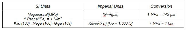
Stress is described as the internal force acting upon a specific cross sectional area within an object. The equation below shows that stress is equal to the force divided by the area. The units of stress are in “psi” or “kips” for imperial units and Megapascal for SI units.

You may encounter both sets of units on the PE exam, so you should be familiar with both and should commit these conversions to memory.
The strength of a material with respect to stress is the maximum stress that a material can withstand before failing. For brittle materials, failure occurs at ultimate stress.

For ductile materials, the maximum stress for a design could be the yield stress, because an object will no longer perform to design if it passes the yield strength and becomes permanently deformed.

On the PE exam, you should be careful to make sure you use the correct maximum stress for the correct type of material and situation. The following two graphs illustrate the difference between the yield stress and ultimate stress for brittle and ductile materials.
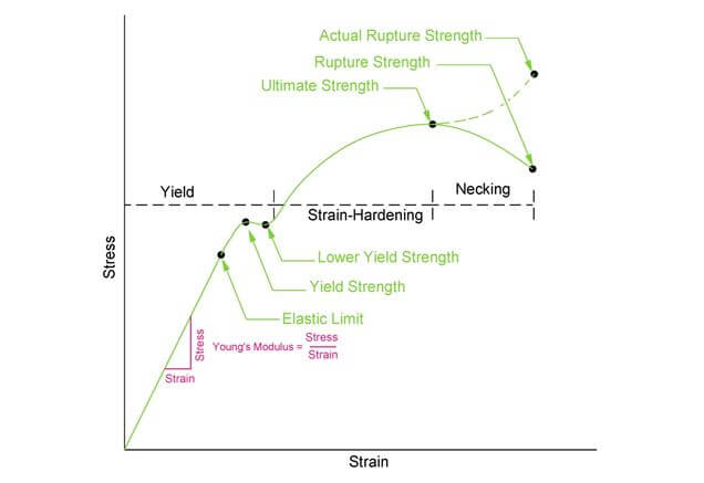
Figure 1: This figure shows the stress and strain relationship for ductile materials. The yield strength is typically used as the maximum design stress for ductile materials.
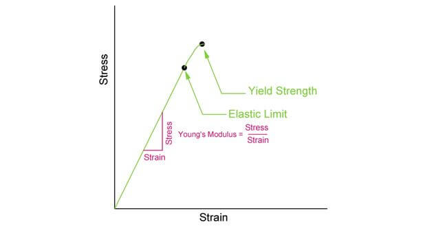
Figure 2: This figure shows the stress-strain relationship for brittle materials. The yield strength is equal to the ultimate strength and is typically used for maximum design stress.
Stress will be discussed more in the tension and compression paragraphs.
Strain
Strain is the result of the stress. Strain is the deformation of the object in the direction of the force. An example is a pipe being stretched, where the strain would be observed in the longitudinal direction (length of pipe). Strain can also result due to thermal expansion/compression as shown in the Thermal Stress and Strain paragraph, which will be discussed later. Strain is measured as the change in length of the object, divided by the original length of the object.

The modulus of elasticity is a number that describes the pipe’s resistance to being deformed. A large modulus of elasticity means that it will take more force to deform the pipe. There are two types of modulus of elasticity. The Young’s Modulus E describes the tensile elasticity or the elasticity along the length of the pipe, when the pipe is stretched. The shear modulus describes the shear deformation elasticity, which is the ability of a material to slide in opposite, parallel directions, imagine a pipe twisting. If you need more information on these terms, refer to the Material Properties section.

These values are dependent on the material. Be sure to locate a table of these values for various materials (steel, copper, aluminum, iron) in your Mechanical Engineering Reference Manual or your Machinery Handbook.
Tension & Compression
On the PE exam you may encounter problems where an object is under a force due to tension or compression. A tension force is a force that attempts to pull a material apart. A compression force is a force that squeezes a material together. The forces due to tension and compression will cause a stress within the material that is equal to the force divided by the cross sectional area that is perpendicular to the force.
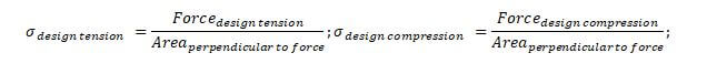
On the PE exam, you will use the above equations and compare the design stresses, design forces and design areas to the strength of the material. The strength of the material will vary for each material. The strength of the materials in tension/compression will be equal to the ultimate stress for brittle materials and yield stress for ductile materials.
In some cases, certain brittle materials will have varying strengths under tension and compression. Thus there are two ultimate stresses used to determine the strength of a material.

You should read the question carefully and ensure you are comparing the correct strength of material value to your design tension or compression.
Yield Point
The yield point is defined as the point on the stress-strain graph when the straight line relationship no longer applies. After this point, the Young’s Modulus cannot be used to solve problems. The yield point also describes the point when permanent deformation will occur to ductile materials and this point is typically the point of fracture for brittle materials. Thus in practice the yield stress point is used to determine the maximum load of an object.

Ultimate Tensile Strength
PE exam problems that use ultimate tensile strength are problems involving the maximum stresses when an object is under tension before an object breaks. Ultimate tensile strength can also be given for compression loading, although this is less likely in practice. As previously shown on the Stress-Strain graphs, the ultimate tensile stress occurs near the elastic region of the graph while the ultimate tensile stress is outside of the elastic region of the graph.
Elongation
Elongation type problems use either the Young’s Modulus or the Stress-Strain graph to determine the amount of elongation of the object. Elongation is the lengthening of an object that is subject to tension.
When a component elongates due to a stress, the component also contracts in the axis perpendicular to the elongation. The direction of the stress in tension will cause a positive longitudinal (axial) strain and a negative contraction in the lateral direction called lateral strain. The ratio of this elongation and contraction is called Poisson’s ratio.

Poisson’s ratio can also be used to show the relationship between the modulus of elasticity in tension/compression and the modulus of elasticity in the shear direction. The equation that governs this relationship is shown below.

Thermal Stress & Strain
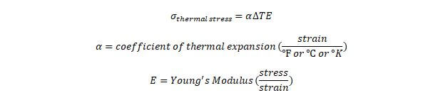
As previously discussed in the Material Properties section, an increase in temperature can cause an object to expand and a decrease in temperature can cause an object to reduce in size. This change in dimensions is called thermal strain. As previously discussed thermal strain can be calculated with the equation below, which determines the change in length of an unrestrained object.

If this object is restrained, then the expansion/contraction will not result in a change in dimensions but will result in a change in the internal stresses of the object. An increase in temperature will cause internal stresses to rise in a restrained object and a decrease in temperature will cause internal stresses to drop. These internal stresses due to temperature changes are called thermal stress. Thermal stress is governed by the equation below.
Shear
Shear stress is the stress that is in parallel to the area, as opposed to stress in tension or compression which acts perpendicular to the area. The figure below shows a force that acts in parallel to the area. The shear stress is defined as the shear force divided by the area.


Figure 3: Shear stress acts in parallel to the cross sectional area of the object. Stress in tension or compression acts perpendicular to the cross sectional area.
The shear properties for materials are determined through a series of tests to create the shear stress-strain graphs, similar to the stress-strain graphs previously discussed. Similarly, there are also shear yield strengths, shear ultimate strengths and a shear modulus of rigidity.

The shear modulus of rigidity is found by applying a series of shear forces to a material and measuring the strain. The slope of the line that relates shear stress to shear strain is equal to shear modulus of rigidity, which can also be known as the shear modulus of elasticity.

Shear Strain
Shear strain is similar to the strain previously discussed, except that shear strain is the change in angle of the object as opposed to the change in length/width of the object. Shear strain is measured in radians.
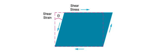
Figure 4: Shear strain is shown as the angle change.
The change in angle for the above figure can be shown with the following equation.

Bending
Bending occurs when slender objects are used to support loads perpendicular to their length. The most common type of problem that you will encounter on the PE exam is the bending of beams. Section 3.0, Engineering Science and Mechanics, introduced the bending of beams and the equations that govern the various situations that you may encounter. This section will tie together the material properties and the beam diagrams to determine the strength of a beam during bending.
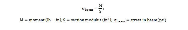
Once you use the force and moment diagrams from the previous section to determine the maximum forces and moments in the beam, then you can determine the stress in the beam through the following equation. The maximum stress in the beam is equal to the maximum moment divided by the section modulus of the beam. The section modulus will be defined later in this section. The equation to find the stress in a beam is shown below.
Section Modulus
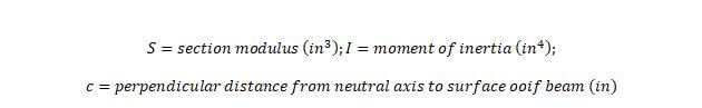
The section modulus is a function of the geometry of the cross section of a beam. The section modulus is defined as the moment of inertia divided by the perpendicular distance from the neutral axis of the beam to the surface of the beam.

The section modulus is a measure of the strength of the beam’s geometry. A larger moment of inertia or a smaller distance between the center of gravity and the surface will result in a stronger beam than a beam of equal material properties but a smaller moment of inertia or a larger distance “c”. This is reiterated with the next figures.
The cross section of a beam will determine its moment of inertia. Thus a larger cross section will result in a larger section modulus, which will result in lower stresses in the beam.
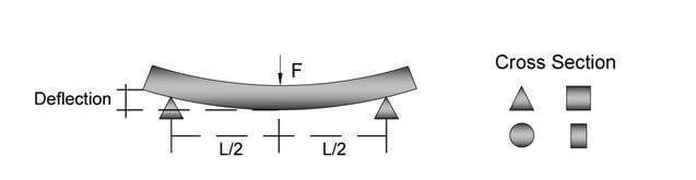
Figure 5: The strength of a material during bending is dependent on the length of the object, the material properties and the cross section of the object.
The following figure shows that the stresses due to tension and compression in a beam during bending vary based on the location relative to the center of the cross section of the beam. The top and bottom of the beam will experience the highest levels of stress.
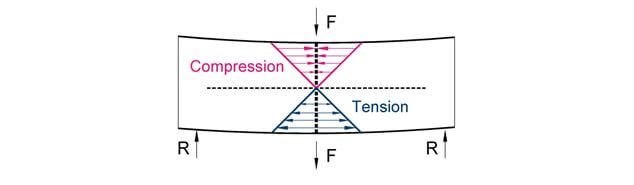
Figure 6: Cross section of a beam in bending. The maximum stress will occur at the surface of the beam. The distance from the center of the beam to the surface uses the variable, “c”.
The final maximum beam stress equation will be the maximum moment multiplied by the maximum distance, “c” divided by the second moment of area (moment of inertia).

The information shown on this website is a sample of the material provided in the technical study guide and sample exam. See the STORE to buy the products for continuation on Bending for the Mechanical Machine Design & Materials PE Exam.
Buckling
Buckling occurs when an object is subject to compression and as the compressive load increases, there is a quick bowing movement outwards, perpendicular to the direction of the loading. This situation becomes very unstable and the support will most likely be either deformed or unable to carry the force. A material’s stress during buckling will most likely be less than the stress required to fracture or crush the same material in compression, which is typically the ultimate tensile stress or yield stress.
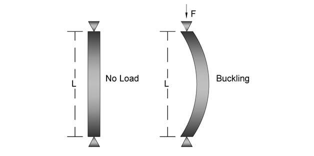
Figure 7: Buckling occurs when the length of a material is typically an order of magnitude greater than the width or diameter of the material.
Buckling occurs when a long, slender object is under compression. Mathematically, you must first confirm that an object is slender through the following steps.
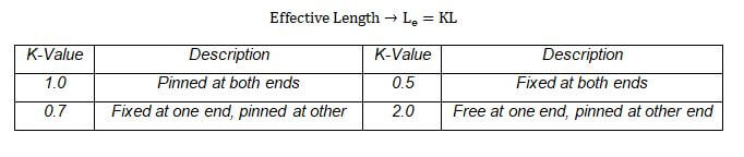
Step 1: Find the effective length
The first step is to find the effective length of the object. The effective length will depend on the length of the object and the K-constant which depends on how the object is situated. If the object is fixed then the effective length will be smaller as compared to when one side of the object is fixed and the other is free. This will cause the effective length to increase. The following table provides the various situations and their corresponding K-constants.
Step 2: Find radius of gyration
The radius of gyration compares the moment of inertia and the cross sectional area. The larger cross sectional area will cause the radius of gyration to increase, which means the object is less slender. You will need to compute the radius of gyration for both the x and y axis and use the minimum radius of gyration for the next step.

Step 3: Find the slenderness ratio
Once you have the minimum radius of gyration and the effective length, then you can find the slenderness ratio with the following equation.

Step 4: Find column constant
The column constant takes into account the modulus of elasticity and the yield stress of the material. A material with a larger yield stress will mean the column is much stronger and thus the column can be longer before it will be considered slender and therefore subject to buckling.

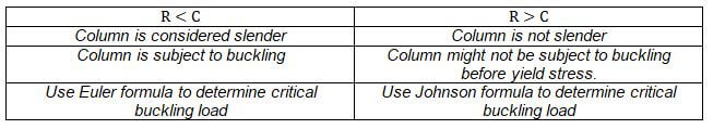
Step 5: Compare slenderness ratio and column constant
Finally, compare the slenderness ratio and column constant. If the slenderness ratio is less than the column constant then the object is considered to be slender and long. Thus the column will be subject to buckling.
The information shown on this website is a sample of the material provided in the technical study guide and sample exam. See the STORE to buy the products for continuation on critical buckling load for the Mechanical Machine Design & Materials PE Exam.
Torsion
Torsional loading is the act of twisting an object, typically a rod or shaft in the Machine Design field. When the shaft is twisted, a torque is applied that causes the shaft to deform as shown in the figure below. The solid line is the new twisted axis and the dotted line shows the original axis. The angular difference between these two lines is called the angle of twist.
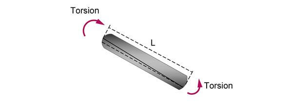
Figure 8: Torsion occurs when an object is twisted about its longitudinal axis. The dotted line is the original longitudinal axis and the solid line is the new axis after torsion.
Similar to beams during bending, the shear stress experienced in the shaft will vary based on the location from the center of the longitudinal axis of the shaft. The maximum shear stress will be at the surface of the shaft.

Figure 9: The maximum torque on a shaft occurs at the surface. The center of the shaft experiences zero torque.
The shear stress at any point from the origin to the radius R can be found with the ratio of the location to the total radius of the shaft. This equation shows you that the shear stress will be at a maximum at the surface of the rod or shaft.


The information shown on this website is a sample of the material provided in the technical study guide and sample exam. See the STORE to buy the products for continuation on Torsion for the Mechanical Machine Design & Materials PE Exam.
Fatigue
The stress, strain, shear, bending, buckling and torsion topics discussed the strength of materials based on a maximum one-time load. However, the strength of materials is not only characterized by this maximum loading but also by the maximum cycles of repeated loading. Fatigue describes the relationship between cycles of loading and the magnitude of the loading. A small load with a small number of cycles of applying this load will not fatigue an object but a large load with a large number of cycles of applying this load will fatigue an object.
This repeatedly applied load will cause the object to fail at typically a smaller value than the ultimate tensile strength or yield point, which was discussed earlier. This is why the study of fatigue in Machine Design and Materials is important. Fatigue typically occurs when objects are subject to cyclic loading throughout its life, where the stress on the object varies in a sinusoidal waveform from a maximum level in one direction and then a maximum level in the opposite direction.
The sinusoidal shape is not as important as is the maximum and minimum values of the shape. These maximum and minimum values determine the alternating stress and mean stress values. Alternating stress is defined as the difference between the maximum and minimum stress values acting upon the component. The mean stress is the average value of the stress values acting upon the component.

These two values will be used to construct the Goodman diagram in the next section.
The information shown on this website is a sample of the material provided in the technical study guide and sample exam. See the STORE to buy the products for continuation on the Goodman diagram for the Mechanical Machine Design & Materials PE Exam.
Failure Theories
Failure can mean a component has been completely fractured; permanently distorted or its function has been compromised. In Section 4.0 Material Properties and earlier in this section, various strengths of material properties have been presented. Unfortunately, these strengths which can be used to determine the stress levels at which failure will occur apply only to simple loadings like tension that occurs in one axis. In real life situations and for most of the PE exam, the simple loadings can be assumed. However, there may be a couple of questions on the PE exam that test your understanding of the major failure theories that are commonly used in practice.
The information shown on this website is a sample of the material provided in the technical study guide and sample exam. See the STORE to buy the products for continuation on Failure Theories for the Mechanical Machine Design & Materials PE Exam.