- HOME
- FE EXAM
- PE EXAM
- DESIGN TOOLS
- COURSES
- STORE
- ABOUT
- CONSULTING
![]()
Engineering Pro Guides is your guide to passing the Mechanical & Electrical PE and FE Exams
Engineering Pro Guides provides mechanical and electrical PE and FE exam technical study guides, practice exams and much more. Contact Justin for more information.
Email: contact@engproguides.com
EXAM TOOLS
Vibration for the
Machine Design & Materials P.E. Exam
by Justin Kauwale, P.E.
Introduction
Vibration accounts for approximately 3 questions on the Machine Design & Materials Mechanical PE exam. Vibration on the PE exam accounts for only three questions, but the topic of Vibration in the Machine Design field is important and centers on creating a design that limits unwanted vibrations through damping. In order to create this ideal design, you must first understand the mathematical model that governs vibration in order to characterize, predict and analyze vibrations. Next, you must understand the effects of damping on vibration. Finally, for the purposes of the exam you must understand how to apply this analysis to various loading configurations (torsional and linear) and various vibration scenarios (forced and free vibrations).
The information shown on this website is a sample of the material provided in the technical study guide and sample exam. See the STORE to purchase these items.
Vibration Basics
The topic of Vibration Analysis encompasses motion in machine design objects that are characterized by periodic, sinusoidal functions. Each object is characterized by inertia, stiffness or elasticity, damping and imparted energy or work. The sinusoidal functions that govern the movement of these objects take into account the characteristics of the machine design object.
Before these characteristics are discussed, you should first understand some basics of sinusoidal functions. First, these sinusoidal functions occur in periods or cycles. The number of cycles or periods completed in one second is defined as the frequency. Frequency is given in units of hertz (seconds-1). A frequency of 60 hertz corresponds to a period of 0.0167 seconds, which means that one cycle is completed in 0.0167 seconds.

Another basic term that is closely related to frequency is angular frequency. Angular frequency is the rotational frequency and is given in terms of radians per second. For example, if one rotation is completed in one second, then the angular frequency is 2π. Angular frequency is related to physical frequency through the following equation. Angular frequency is used for rotational machine design objects like shafts.

Another defining feature of a sinusoidal function is the amplitude. The amplitude can be represented as either a root mean square (RMS) value or a maximum amount. Most often the amplitude will be represented as the maximum amount, however the RMS conversion is provided for completeness. The RMS value is used to find the average or effective value of a constantly varying value. The term RMS is found by taking the sum of “n” number of points along the waveform, squaring each value, summing all “n” values and then taking the square root of the sum.
The fundamental equation for calculating RMS is shown below. The term “yn” is used to represent the y-value that corresponds to an x-value of “n”.

In a basic sinusoidal waveform, the RMS value is determined for an infinite number of “n” points. This value is shown as 0.707 times the peak value of the sinusoidal graph.

The following figure shows a typical sinusoidal graph. The RMS equation applies to this sinusoidal function because there is no damping, which indicates that the maximum amplitude of the function does not change from one period to the next. In practice friction and damping will cause free vibrations to have a reduction in amplitude from one period to the next. In forced vibrations, there may be a consistent sinusoidal function and the second RMS equation shall apply. However, the first RMS equation will apply to both free and forced vibrations.
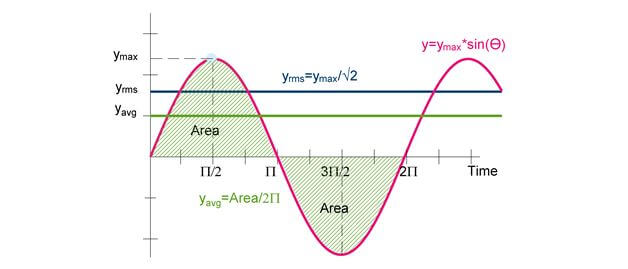
Figure 1: A typical sinusoidal function has a period of 2 and its RMS value is 0.707 times its maximum amplitude.
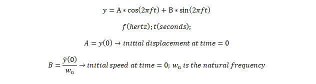
The basic sinusoidal function has the following equation in radians (not degrees) format.
Springs
The simplest type of vibration is a spring. A spring is used as the basis to analyze more complex machine design objects. A spring is described as a system with a spring constant or stiffness (k) and a mass (m). The stiffness is used to characterize the amount of force required to cause a certain amount of deflection in the spring. This is shown in the equation below.

The deflection can be seen in the following figure on the left. The previous equation does not take into account time. The previous equation assumes there is a constant force, F. But if the force imparted on the mass and spring is at a single moment in time, then the result will be an oscillation of the mass up and down as the potential energy due to the compression or elongation of the spring balance with the kinetic energy of the moving mass. The following figure shows how the oscillation of the spring can be modeled as a sinusoidal, periodic function.
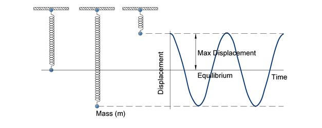
Figure 2: Vibrations can be modeled as a spring. This figure assumes an undamped spring that will oscillate until an external force is applied.
The total energy in an undamped spring remains constant based on the following equations. An undamped spring means that there are no frictional forces or damping forces.

The total energy is equal to the potential energy of the spring at max displacement. At this point the kinetic energy of the mass is equal to zero because the velocity is equal to zero.

The total energy is equal to the kinetic energy of the mass at equilibrium. At this point the potential energy of the spring is equal to zero, because the displacement is equal to zero.

Natural Frequency
The period and natural frequency of the periodic, sinusoidal function will depend on the mass and the spring stiffness. The formula that governs this equation is shown below. The term natural frequency is used because this frequency is only dependent on the properties of the mass and stiffness. Later in this section, forced or disturbing frequencies will be introduced and these frequencies are due to external forces acting upon the spring system. It is critical to determine the natural frequency of the mechanical system, because if a forced or disturbing frequency is close to the natural frequency then resonance will occur and vibrations will be magnified.

Although springs are used as the basis for vibration analysis, all machine design items can be modeled similarly. Each machine design situation has a corresponding, k-value or stiffness based on its geometry, modulus of elasticity and/or shear modulus. A few examples of the stiffness values for the following situations are shown below.
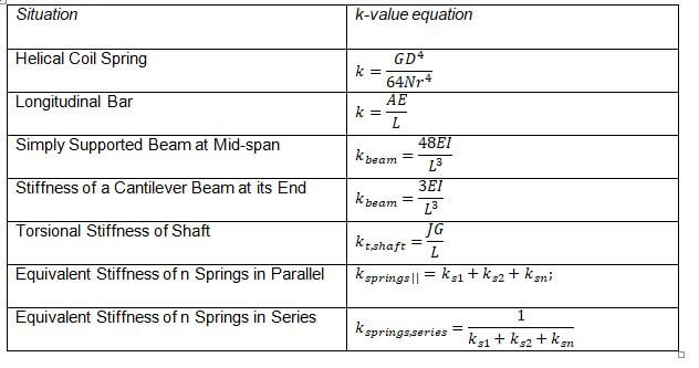
Once you have found the correct k-value, then you can use the k-value to find the corresponding natural frequency with the previous equations. Another way frequency can be expressed is in radians format. In this format the 2-pi term is removed.

The units can be found to be units as shown in the dimensional analysis below. The units for radians are dimensionless, since the definition of radians is the circular arc divided by the radius of the arc. This results in meters divided by meters for US units.
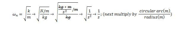
The following shows the dimensional analysis for US units.

Forced Vibration
Once the natural frequency of the machine design system is found, then the forced vibration acting upon the machine design system must be determined. The natural frequency again only depends on geometry and material properties. Forced vibration depends on the external forces applied to the machine design system. In most cases this is due to the rotation of an item, like a rotating shaft. The speed of this shaft is usually given in RPM, which can be converted to frequency with the following equation.

Frequency (Hz) is simply number of cycles or revolutions completed in a second. This frequency can also be converted to radians by dividing by the 2-pi term.

This frequency is called the disturbing frequency or the forced frequency. The natural frequency and the disturbing frequency will determine the amount of damping required, as shown in the next section.
Damping
Once the natural and disturbing frequencies have been determined, it is necessary to design an appropriate damping system to reduce unwanted vibrations. The previous discussions and equations assumed that the mechanical system was undamped. If no energy is lost or dissipated in friction or other resistance during oscillation, the vibration is known as undamped vibration. If any energy is lost, then it is called damped vibration. In many physical systems, the amount of damping is so small that it can be disregarded for most engineering purposes. However, consideration of damping becomes extremely important in analyzing vibratory systems near resonance.

Figure 3: A spring system can be modeled similar to the undamped system, except for the addition of the damping coefficient.
There are three main types of damping, (1) Coulomb Damping, (2) Hysteresis or Inherent Damping and (3) Viscous Damping.
(1) Coulomb Damping: This type of damping force is constant throughout the entire displacement and also does not depend on the velocity of the system. This type of damping is also called dry friction damping. The best example is a mass moving on a surface. The frictional force acting upon the mass does not depend on the speed or location of the mass. This type of damping is not used on the PE exam.
(2) Hysteresis or Inherent Damping: This type of damping uses the elastic properties of elastomers to dampen vibrations. This is typical of rubber pads or rubber bushings.
(3) Viscous Damping: This type of damping is used on the PE exam. This type of damping is typical of spring vibration isolators. This type of damping changes its force in response to the velocity and deflection from equilibrium. The following discussions only apply to viscous damping.
The damping value is shown in the previous figure as a damping coefficient labeled “C”. This value has the units as shown below.

The critical damping coefficient is the value that causes the machine design system to most quickly return back to equilibrium. This value is found through the following equation. Notice that similar to the natural frequency, the critical damping coefficient is only a function of “k” and “mass”.
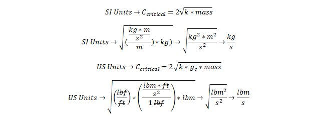
The actual damping coefficient will be determined by the manufacturer of the vibration dampener or spring.
Damping Ratio
Once the critical damping coefficient and actual damping coefficient are found, then the damping ratio can be computed. The damping ratio has dimensionless units and it describes how slowly or quickly a system is returned to its original conditions after a temporary change to the original conditions. The damping ratio is defined as the ratio of the actual damping to the critical damping.

The ratio will determine the damping classification of the machine design system into one of the four categories.
Undamped
If there is no damping then the damping ratio will equal 0. This situation was previously discussed and is called undamped. There will be no decay in the sinusoid and the amplitude of the sinusoid will remain the same as time progresses. The undamped equation was previously given, but is shown again here in a different format, since natural frequency has been introduced.

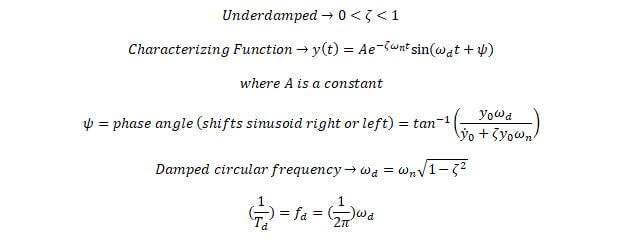
Underdamped
If the ratio of the actual damping and critical damping is in-between 0 and 1, then the system will be underdamped. The sinusoid will decay slowly and with oscillations. The equation that governs an underdamped system is shown by the characterizing function below.
Critically Damped
This classification occurs when the actual damping equals the critical damping value. The sinusoid will exponentially return back to equilibrium.

Overdamped
The final classification occurs when the damping ratio is greater than 1. The machine design system will decay exponentially back to equilibrium but not as fast as the critically damped classification.

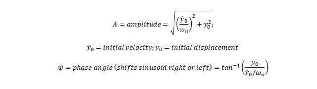
The equations for the constants are not shown because this would make the equations take longer than 6 minutes to solve on the PE exam. The constants are a function of initial displacement and velocity. In most problems, you will be given the constants in order to focus on the more critical concepts in these equations like damping ratio, natural frequency and damped frequency.
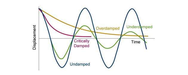
Figure 4: There are four classifications of damped systems that depend on the damping ratio. This graph shows the different effects of the different damping classifications.
Transmissibility
Transmissibility is a term used to describe the effectiveness of the damping. Transmissibility is the ratio of the vibrational force that is measured after damping to the ratio of the vibrational force entering the machine design system. A low transmissibility means that the damping system is effective as opposed to a high transmissibility means that the damping system is ineffective. The equation to determine transmissibility is shown below. In this equation a new term called Frequency Ratio is introduced. This is the ratio of the damped frequency to the natural frequency. The other term shown is the damping ratio.

The equation above can also be shown in graphical terms. There may be a chance that you will be given this graph on the exam and a question may involve finding the transmissibility given the damping ratio and frequency ratio.
Also you should be familiar with typical damping factors. Rubbers and neoprene pads have larger damping factors of around 0.05 to 0.15. Steel and other metal springs have order of magnitudes lower damping factors around 0.005. This means that to achieve a lower transmissibility for these metal springs, you need a smaller frequency ratio as compared to rubbers and neoprene pads that will need a larger frequency ratio.
For really small damping ratios, the transmissibility is reduced to the following equation.

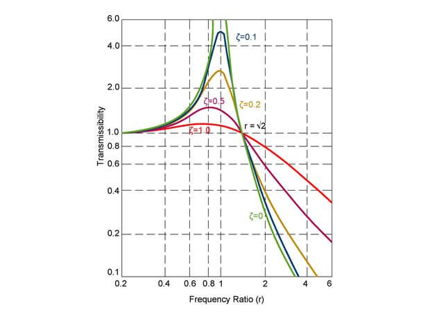
Figure 5: This graph shows the transmissibility as a function of various frequency ratios for different damping ratios.
Magnification Factor
The magnification factor is focuses on the transmissibility values greater than one in the transmissibility graph. The magnification factor indicates a situation when the forced vibration is magnified by the damping system.

Transmissibility values greater than one occur when the following two requirements are met, (1) the damping ratio is less than 1 and (2) when the frequency ratio is less than one. These requirements are met in the upper left quadrant of the transmissibility graph. The magnification factor increases exponentially in this portion of the graph. Transmissibility begins to be less than one when moving from left to right, when the frequency ratio is equal to root 2.

This point is an important location to remember. This point indicates that transmissibility will become less than 1 when the damped frequency is root 2 times greater than the natural frequency. This is the minimum damped frequency.
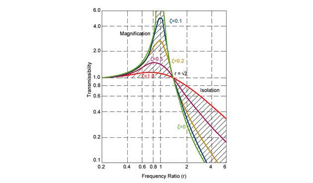
Figure 6: This figure reiterates that magnification occurs in the upper left quadrant and isolation occurs in the lower right quadrant.
Vibration Applications
The first discussion on natural frequencies assumed the vibration was a free vibration. Free vibration implies that there is a single movement which causes the object to vibrate and after that single movement, there are no external forces acting upon the system, except for gravity, springs, dampeners, etc. Forced vibrations occur when an object undergoes a repetitive ongoing external force. An example of a repetitive, ongoing, external force would be the rotation of a fan blade or pump impeller. The vibration caused by the pump or fan is a, example of forced vibration.
Vibration Isolation
In practice, your machine design should have vibration isolation to protect the equipment from unwanted vibrations. For the purposes of the exam you should be familiar with the vibration isolator selection process. The best free location for this information are the following manufacturer’s websites.
Karman Rubber: http://karman.com/
Tech Products: https://www.novibes.com/
Shock and Vibration Components: http://www.vibrationmounts.com/
The basic process of selecting a vibration isolator will also be discussed next. Vibration isolators are selected to reduce the vibration from equipment by storing the incoming energy. The first step is to find the disturbing vibration frequency. This is the frequency at which the equipment is vibrating. For example, fans, pumps and motors will have a frequency equal to their RPM. A typical rotational speed for motors is 1,800 RPM. This corresponds to a frequency of 60 HZ.

If there is more than one disturbing frequency, then you should find the lowest frequency. If the vibration isolator is designed for the lowest frequency, then all other higher frequencies will also be isolated.
The next step is to choose the transmissibility of the vibration isolator. The transmissibility is the amount of vibrations that are transmitted through the isolation system. This value is the inverse of the isolation provided by the vibration isolator. The amount of transmissibility selected will depend on the code requirements or the sensitivity required of the machine design.


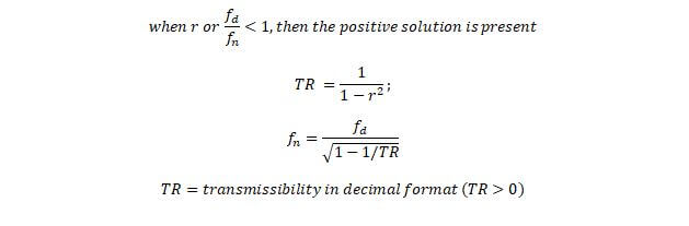
Once you have selected the transmissibility, the next step is to find the natural frequency of the vibration isolator that is required to achieve this transmissibility. Typically you can use the following equation for negligible damping.
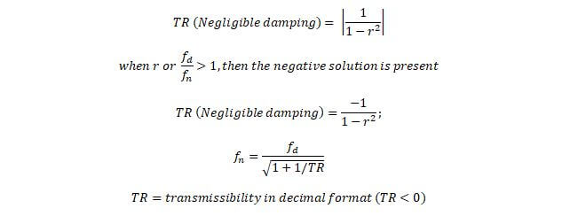
The following is provided for completeness, but in most cases the frequency ratio for isolation will need to be greater than one. If the frequency ratio is less than one, then magnifcatino occurs.
Finally, you can use the required natural frequency to select the vibration isolator. There are other factors that come into play when selecting a vibration isolator like material life, corrosion, support weight and deflection. For the purposes of the exam you should be familiar with the support weight and the deflection amount.
Support Weight: The vibration isolator must be capable of supporting the weight of the machine design equipment when it is not vibrating.
Static Deflection: The isolator will also deflect from its equilibrium deflection based on the natural frequency of the isolator. This is the minimum required deflection to obtain the required natural frequency. An isolator with a larger deflection will have a lower natural frequency.

Stiffness (k): Once you have the minimum deflection, then you can find the required maximum stiffness of the vibration isolator with the following equation.

Acoustics
Vibrations will cause noise that may be deemed unwanted. The amount of noise created due to vibrations and the effects of dampening on noise can be quantified with the following equations. The transmissibility is used to find the amount of decibels produced. Typically sound will be given for a piece of equipment and then you can calculate the transmissibility after the vibration isolator is installed. The transmissibility will cause the decibels of the equipment to be reduced in accordance with the below equation.
