![]()
Engineering Pro Guides is your guide to passing the Mechanical & Electrical PE and FE Exams
Engineering Pro Guides provides mechanical and electrical PE and FE exam technical study guides, practice exams and much more. Contact Justin for more information.
Email: contact@engproguides.com
EXAM TOOLS
Support Knowledge for the
Machine Design & Materials P.E. Exam
Introduction
Supportive knowledge accounts for approximately 10 questions on the Machine Design & Materials Mechanical PE exam. The Supportive Knowledge topic is one of the hardest topics to study because of its wide range. However, since there are 10 problems in this section and there are 5 outline topics in the NCEES outline, you can make the assumption that on average there will be two questions from each of the topics.
The five topics are (1) Manufacturing Processes, (2) Fits and Tolerances, (3) Codes and Standards, (4) Computational Methods and (5) Testing & Instrumentation. Through the analysis of finding 6 minute type problems of the most commonly encountered situations in the Machine Design field under these topics, you can decipher the most likely types of questions on the PE exam in these very broad topics. This will help to put you in the best situation to get these problems on the PE exam correct.
The information shown on this website is a sample of the material provided in the technical study guide and sample exam. See the STORE to purchase these items.
Manufacturing Processes
For the purposes of the PE exam, you should not need to be familiar with the details of the manufacturing processes as if you were in the manufacturing field. This is because the manufacturing processes category is vast and it does not relate to the application of the Machine Design skills and concepts that were tested in the rest of the PE exam. All the other sections and topics on the PE exam focus on using standard components and materials and not manufacturing custom items. For example, standard bolts and screws are used as opposed to creating custom bolts and screws. This analysis should tell you that only the main concepts of the NCEES outline topics under manufacturing processes are required and not details that you would learn from being in the manufacturing field.
The three main Manufacturing Processes topics presented in the NCEES outline are shown below, (1) Machining, (2) Molding and (3) Heat Treatment.
Machining
Machining is a broad term used to encompass any machine process that removes material from a component. The most common machining processes include turning, drilling and milling. Questions on the PE exam could be general questions that test your knowledge of the various machining processes and when they are used. However, there could be some quantitative questions that are shown in the list below.
1. Turning: Turning is used to reduce the diameter of a cylinder. The machine used to carry out this process is called a lathe. (The next discussion makes the assumption that you are familiar with a lathe.) One possible quantitative PE exam question on this topic could ask you to find the new diameter of the cylinder, based on the depth of the cut. The original diameter will be reduced by 2x the depth of the cut.
2. Boring: Boring is used to enlarge existing holes. A similar type of diameter question can be asked for boring as was asked for turning.
3. Drilling: Drilling is used to create a round hole.
4. Milling: Milling is the process where a machine component is fed past a rotating cutting tool. The tool removes material along the direction of the feed.
Molding
Molding is the process where metal is heated to liquid form and then poured into a mold. The liquid turns to a solid in the shape of the mold. Professional engineers rarely encounter the need to create molds and it is also less likely that you will need to personally oversee the mold creation and melting process.
Heat Treatment
Heat-treating is the process of heating metals to specific temperatures at specific rates in order to change the performance and material properties of the metal. This is done by changing the microstructure of the metal and/or the composition. The chemistry that takes place and the details in the microstructure is outside the scope of the PE exam. For the exam, you should be focused on the most popular heat treatment methods and should have a general concept of these processes. The major heat treatment processes are annealing, hardening, strengthening, tempering and quenching. These processes generally either make materials softer or harder, stronger or weaker, ductile or brittle.
Annealing
The process of annealing involves heating a material to a specific temperature and keeping the material at that temperature for a set time. Finally, the temperature is slowly reduced back to room temperature. The purpose of annealing is to change the metal to make it more ductile and workable for machining and bending. There are multiple types of annealing, but the basic process involves
For the purposes of the PE exam, it is important to know the below diagram. In the annealing process, steel is heated to a specific temperature suitable for the type of annealing.
Full Annealing: The metal is raised to about 50 C above the austenitic temperature and then slowly cooled by slowly reducing the temperature of the heat source. This is shown as the downward sloping curved band. This produces a coarse pearlite, which is described as a ductile material, but with a relatively lower yield and tensile strength.
Normalizing Annealing: Normalizing occurs at temperatures above the critical temperature. Then the temperature is held for a long period of time and then cooled in ambient air, which cools the metal at a much quicker rate. This produces a fine pearlite, which is described as hard and stronger material but with lower ductility.
Process Annealing: The metal is heated to a temperature just below the ferrite-austenite or austenite-cementite line. The temperature is held for a long time and then slowly cooled by slowly reducing the temperature of the heat source. This produces a soft and ductile material for machining. This is done to allow for the cold working of the material. Cold working is the bending and machining of the material at room temperature.
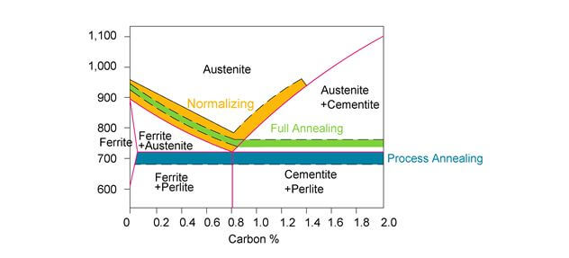
Figure 1: The three main types of annealing differ based on their heating temperatures and time to cool. Process annealing occurs below the austenite temperature critical point, as shown in blue. Normalizing occurs slightly above the transformation curve to austenite, as shown in orange. Full annealing occurs slightly above the transformation curve to austenite+cementite and austenite, as shown in green.
Time Temperature Transformation Graph
The previous figure showed an important graph of temperature vs. carbon %. This is another important graph that must be understood for heat treatment.
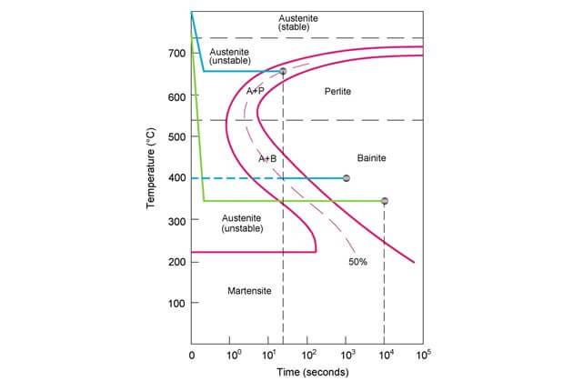
Figure 2: The time temperature transformation (TTT) graph shows how the material changes based on how long the material is held at a certain temperature. This graph is only true for a specific carbon percentage. Also be sure to recognize that the time axis is in a logarithmic scale.
On the graph, the term martensite is introduced. The other terms were introduced in Section 4.0 Material Properties. Martensite is achieved through rapid cooling, much faster than cooling in ambient air. This rapid cooling is called quenching, which will be discussed later. Martensite is a hard, brittle material with superior strength.
The previous figure showed two paths that will help you to understand how to read the TTT graph.
Green Path: The first path is in green. The metal is at a temperature of 800 C, where it is 100% austenite and stable. It is then rapidly cooled to about 350 C, as shown as the steep downward slope. At this point, it is still 100% austenite but it is now unstable. Then it is held at this temperature till 104 seconds. At this point, it is 100% bainite and when it is cooled back down to room temperature, it will be 100% bainite.
Blue Path: In this path, the metal is at a temperature of 800 C, where it is 100% austenite and stable. It is then rapidly cooled to about 650 C, as shown as the steep downward slope. At this point, it is still 100% austenite but it is now unstable. Then it is held at this temperature till about 20 seconds. At this point, it is 50% austenite and 50% perlite. Next, the metal is rapidly cooled down to 400 C. At this point, the 50% perlite is stable, but the 50% austenite is unstable. It is then held at this temperature till 103 seconds. The 50% unstable austenite is transformed into bainite, which results in 50% perlite and 50% bainite. When it is cooled back down to room temperature, the result will be the stable 50% perlite and 50% bainite.
On the PE exam, you should be able to navigate TTT graphs. These graphs also make it easier to understand the effect of time on the final material property. The next sections will give names to the various ways of cooling metal after it has been heated.
Hardening & Quenching
The most common type of hardening is case hardening. This occurs when carbon diffuses into the metal, which causes an improved and harder material that is able to resist wear and tear. The term, “case” refers to the outer surface of the metal. The inside of the metal remains the same, but the outer surface is hardened.
Hardening is conducted by heating a metal to temperatures similar to the full annealing temperature, such that the pearlite is transformed into austenite. Then the heated austenite must be immediately and rapidly cooled through quenching. This can be seen on the TTT graph that was shown previously. Rapidly cooling through quenching will result in martensite.
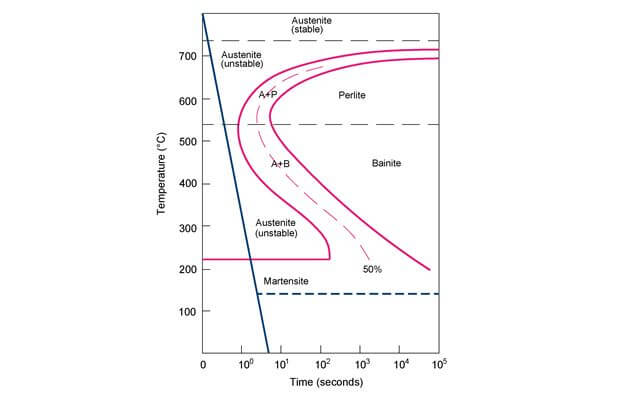
Figure 3: This figure shows quenching from 800 C down to room temperature as the blue solid line. This produces 100% martensite.
In the previous figure there is a solid blue line, which shows the hardening process that produces 100% martensite. However, if the quenching is stopped at 150 C and then held at that temperature, then after a sufficient time the material will change to 100% bainite. This is shown as the dashed blue line at the 150 C temperature.
Martensite is very hard, strong and brittle. Hardening is typically used to create metals that are able to cut other metals. The following graph shows the hardness levels of martensite as a function of carbon percentage. In order to give a sense of scale, pearlite which is produced through annealing has a maximum Rockwell C hardness of around 20.
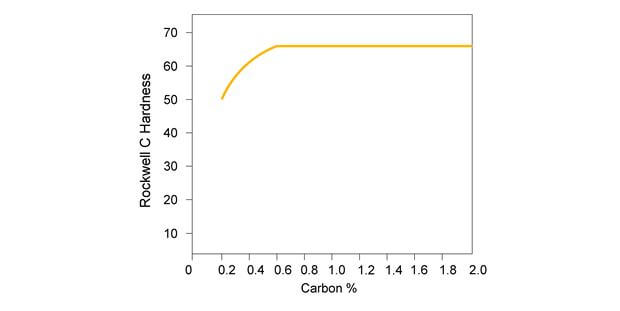
Figure 4: After hardening, martensite is created. This figure shows the hardness of martensite as a function of the carbon %.
Tempering
After a material has been hardened through the previous process, then the material can be tempered to increase its ductility and reduce its brittleness. Martensite is so brittle, that any impact will cause fracture. Tempering involves heating the steel to a temperature that corresponds to the hardness required. Tempering at lower temperatures will cause a lesser reduction in hardness, but will require a longer amount of time to achieve the ductility. Tempering at higher temperatures will cause a slightly higher reduction in hardness, but the tempering process will be finished at a faster rate.
Fits and Tolerances
The fits and tolerances topic is one that is easily tested on the PE exam. You should expect at least two problems in this topic. The problems may be disguised with a lot of extraneous information, but as long as you understand the main concepts in this topic, then you should be able to navigate your way through the extraneous information and arrive at the correct solution.
During the manufacturing process, tolerances are provided to indicate the minimum precision required to allow for a part to operate properly. The fit refers to the clearances between two mating parts. The higher the precision, the more costly a part becomes to manufacture. Therefore, the tolerances and fits are usually given as large a value as possible.
Tolerances
Tolerances are presented as a manufacturered part’s dimension limits. It can either be shown with +/- values or as a range.
In machine design, the tolerances are labeled along with nominal sizes on design drawings for the fabricator. The following figure depicts examples of dimensioning various shapes.
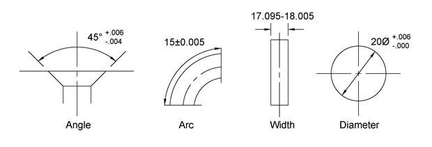
Figure 5: Dimensioning can occur on angles, arcs, lengths, diameters and more.
Fits
Mating two parts together will either require a clearance for smooth movement of one part within another or an interference for a snug, pressure tight fit. Each part is provided with a tolerance. The exam will likely ask you to use a limit dimension from both parts to find a clearance or an allowable dimension for proper operation.
The following image illustrates clearance requirements for a shaft that requires rotation within a hole. If the tolerances were too large, the shaft could potentially be too small to cause unstable rotation or too large causing excessive friction, preventing proper movement.
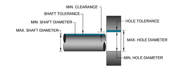
Figure 6: A clearance fit occurs when there is positive clearance between the hole and the shaft.
The following example of interference is a shaft that has a larger diameter than the hole. In this situation, the rod is forced into the hole for a pressure fit, causing one part to be constrained to the other.
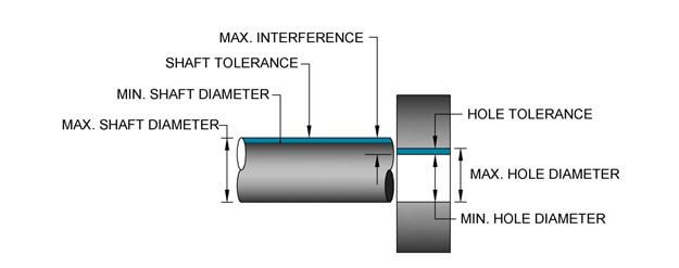
Figure 7: Interference fit in holes occurs when there is a fit with negative clearance between the hole and shaft.
The final type of fit is a transition fit. This type of fit can either have a positive or negative clearance.
Hole Basis and Shaft Basis
In a hole-based system, the size of the hole is kept constant and the shaft size is varied to get a different fit (clearance, transition or interference). The basic size of the hole is taken as the low limit. The high limit of the hole, the low limit of the shaft and the high limit of the shaft are selected to give the required fit. The term basic size is the reference point for the upper and lower limits. Thus if a hole has a minimum value of 25.00, then the basic size is 25.00. If the maximum value is 25.130, then the shaft must be selected to fit into these requirements.
In a shaft basis system, the size of the shaft is constant and the hole-size is varied to achieve the desired fit. The basic size of the shaft is taken as the maximum size of the shaft. The other limit of the shaft is adjusted, along with the limits of the hole to achieve the required fit.
Standard Tolerances
There are various standards for keeping uniform tolerances, one standard is ANSI Standard B4.1, Preferred Limits and Fits for Cylindrical Parts. This is a standard of tolerances for mating parts used in typical applications. The tables below are a sample of tables that could be encountered on the exam.
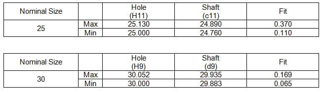
The tables above show various fits, H11/c11 and H9/d9. You can see that the fit on the H9/d9 is tighter than the fit for the H11/c11. The following table shows how the various fits match up to the descriptions. The fits get tighter as you move down. But before you get to the table below you also be aware of how the fit is determined. The maximum fit is found by finding the difference between the maximum hole and the minimum shaft size. The minimum fit value is found by finding the difference between the minimum hole and the maximum shaft size.
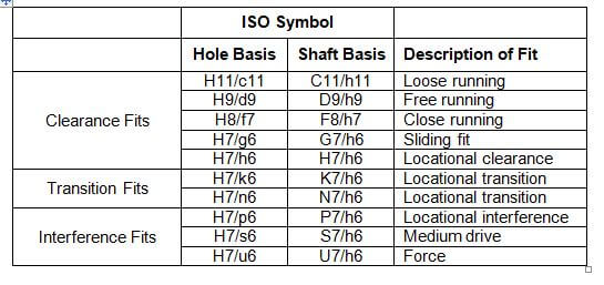
The clearance fits will always have positive fit values or clearance values. The transition fits can have both positive and negative fit values. The interference fits will have negative fit values.
Geometric Dimensioning and Tolerancing
Geometric dimensioning and tolerancing refers to the process of controlling all the aspects of a component to ensure proper fitting and assembly with other components. The important skill within this topic is being able to interpret drawings and symbols. A little bit of this was covered in Section 2.0 Basic Engineering Practice, but that section did not cover tolerances.

Figure 8: This figure is an example of the geometric dimensioning and tolerancing process.
In the figure above, geometry is first stated, followed by the tolerance and in some cases the reference plane or datum. The geometry presented in this example is straightness. This means that the component must be straight (no slope), but there is a tolerance of 0.001. As long as the difference between the minimum and maximum value of this “straight” surface is within 0.001 of each other, then the component meets the requirements of the specification. Section 2.0 Basic Engineering Practice has a list of other geometry symbols like straightness. In addition, the below figure highlights the components that make up the geometric dimensioning and tolerancing method.

Figure 9: This figure shows the basic layout of the geometric and tolerancing method.
Surface Finishes
Surface finishes can also be important in the Fits & Tolerances section, because the roughness of a component’s surface may affect the tolerance of the component. If a tight tolerance is required, then the roughness should be minimized. For example, one of the previous figures showed how the straightness of a surface can be specified to fit within a tolerance. Also if a figure is rough, then it will affect the straightness of the surface. The following method is used to specify the roughness for a component. The roughness value, #3, is shown in units, μm.
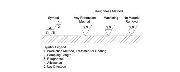
Figure 10: The roughness of a surface can be specified with the above symbology.
Codes & Standards
The NCEES outline does not indicate that you must bring into the PE exam any Codes or Standards. The sample questions also do no reference looking up code or standard information. Based on this information, it is most likely that excerpts of the code will be given in the exam or questions will be based on a general knowledge of the most common codes in the Machine Design field. This section will give you the general knowledge on the most common codes and standards, including (1) ASTM, (2) AWS, (3) ANSI, (4) UL and (5) ASME.
ASTM
ASTM (American Society of Testing and Materials) is a voluntary standards organization that has over 12,000 ASTM standards. For the purposes of the exam, it is not important to know all the standards or even to have access to these standards. However, it is important to know what standards are available and to have an overview of the standards that are specific to the Machine Design field.
AWS
The American Welding Society’s standards covers all aspects of welding, like safety, materials, corrosion, different types of welding, different welding conditions and different welding applications. You should go through the website, to get a feel of the available standards and the type of material that is covered by AWS.
ANSI
American National Standards Institute or ANSI includes information on quality management, medical devices, IT security, fall protection and a lot more topics that are not relevant to Machine Design. The standard that would be most applicable to Machine design would be the one shown below. There should not be any relevant standards from ANSI besides this one: ASME B1.1/ANSI/ASME B1.2/ ANSI/ASME B1.20.1 – Unified Screw and Pipe Threads Package.
UL
UL is an independent safety science company. It tests equipment, materials and products to confirm if they meet the UL safety standards. You will often find the following seal on a product, which indicates that the product has been tested and certified to meet a certain standard.
UL Listing means that UL has tested representative samples of the product and determined that it meets UL’s requirements. These requirements are based primarily on UL’s published and nationally recognized Standards for Safety.
ASME
The American Society of Mechanical Engineers or ASME publishes standards that set the minimum standards for design and construction of various mechanical products.
SAE
The society of automotive engineers have published standards on various mechanical components that are included on the Machine Design PE exam like clutches, brakes, screws, gears, hydraulics, etc. SAE also includes standards on adhesives, lubricants, vibration, material properties, etc. These standards are often times referenced in the Machine Design field, even if the purpose of the design is not automotive. A few examples of when the SAE is used for Machine Design include: (1) SAE Lubricant Grades, (2) SAE Steel Grades and (3) SAE Fastener Grades.
Computational Methods
Computational methods can be used in practice during situations where the stresses, forces, torque or moment cannot be calculated due to multiple unknowns or due to a custom geometry. Fortunately, the PE exam will be unable to test complex problems like these within six minutes, thus you should only have general knowledge of the computational methods available in the Machine Design field.
The NCEES outline mentions CAE, which stands for Computer Aided Engineering. This is the broad topic that covers the other example, FEA, which stands for finite element analysis. In the practice of machine design, FEA is used to conduct stress analysis on components and machine designs with difficult geometries, material properties or forces.
FEA starts by modeling/drawing the 3-D design in a FEA program. Then the FEA program will divide the drawing into a user specified number of finite elements or units that are all connected to one another. The connection between one element and another element is called a node or nodal point. Each of the finite elements can be defined as having a spring factor, “k” that reacts to forces by a set displacement.
Once the geometry is modeled, then you can assign the boundary conditions which are either the specified displacement or force at the boundary. You must also define the constraints. Constraints are points or boundaries that limit motion in translation or rotation. At these points, the 3-D design will not expand or contract due to any force. That point is locked in at that location.
Next, you must define the material properties for the design. This would include items like thermal expansion, strength, elasticity, etc.
Finally, you must assign the loads that will act upon the model. This may be vibration, thermal stress as shown as a change in temperature, stresses or all of the above.
The FEA program will take into account all of these inputs and will output the stress and strain within each finite element. You will be able to tell the localized stresses and strains at any point within the 3-D design in order to determine the weak points in your design.
One of the more popular Machine Design FEA program is ANSYS. The link to the website is shown below.
Link: ANSYS FEA
If you want more background knowledge on FEA, then you can refer to this link. However, if you are short on time, then you should focus on other areas of the exam that have a larger impact on whether or not you pass the exam.
Link: Background FEA Theory
Testing & Instrumentation
Similar to the Manufacturing Processes topic, the topic of Testing and Instrumentation in the Machine Design field is vast. There are some professionals in this field who solely work in Testing and Instrumentation. However, you should not have the same technical knowledge as these professionals, but you should have a general concept of the various tests and the instruments used to conduct these tests. The purpose in having this general knowledge is that you will most likely need to interpret the results of these tests as opposed to the detailed knowledge required to conduct these tests.
The following website has a lot of good information on all the various testing equipment and the different types of tests that can be conducted on materials.
Link: Types of Testing
Link: Testing Equipment/Instrumentation
There are tests for all the material properties that were discussed in Section 4.0 Material Properties. These tests include ultimate strength, compression strength, creep, tensile strength, ductility, elasticity, hardness and shear strength. Adhesive tests include peel strength and adhesion testing. Other less common tests include friction and coefficient of friction testing.
The equipment used to conduct these tests include gauges to measure force and strain, universal test machines, hardness testers and friction testers.