- HOME
- FE EXAM
- PE EXAM
- DESIGN TOOLS
- COURSES
- STORE
- ABOUT
- CONSULTING
![]()
Engineering Pro Guides is your guide to passing the Mechanical & Electrical PE and FE Exams
Engineering Pro Guides provides mechanical and electrical PE and FE exam technical study guides, practice exams and much more. Contact Justin for more information.
Email: contact@engproguides.com
EXAM TOOLS
Joints & Fasteners for the
Machine Design & Materials P.E. Exam
by Justin Kauwale, P.E.
Introduction
The section Joints & Fasteners accounts for approximately 12 questions on the Machine Design & Materials Mechanical PE exam. The joints and fasteners section discusses the various methods of connecting the mechanical components that were discussed in the previous section. The primary types of PE exam questions center on the strength of these joints and fasteners. This can involve finding the amount of stress experienced in the joint or fastener due to a load or it can be finding the maximum capable stress of the joint or fastener. Another typical practice question is determining the size of the joint and fastener required to achieve a certain strength or design load. The typical skills involve the following:
(1) Welding & Brazing: Selecting an appropriate width/length of a weld or the appropriate filler material.
(2) Bolts, Screws & Rivets: Selecting the bolt, screw or rivet diameter, length or material.
(3) Adhesives: Selecting the adhesive area or adhesive material.
The information shown on this website is a sample of the material provided in the technical study guide and sample exam. See the STORE to purchase these items.
Welding & Brazing
Welding and brazing are methods of joining two metal pieces together. Welding joins the metals together through fusing, where the two metal pieces are melted and mixed together along with a filler material. Brazing is different because the two metal pieces are not melted together. In brazing, a filler material is melted and creates a bond with itself and the two metal pieces, thus joining them together. Brazing does not melt the two metals because a lower temperature is used to selectively only melt the filler material.
Welding and brazing both have their advantages and disadvantages, but choosing between the two is not the purpose of the PE exam. You will most likely be tested on the practical applications of welding and brazing with problems that can be completed in 6 minutes. This criteria and the NCEES outline, narrows the material down to the stresses in the various types of welding and brazing joints. Each joint has a different method of calculating its strength.
Butt Weld – Tensile Stress
A butt weld occurs, when two metal pieces are in the same plane and their ends are welded together.
A typical problem may ask you to find the stress in the weld due to an external tensile force that is in the same plane and concentric. The following equation can be used to find the stress in a weld, due to an external tensile force. The figure below shows a weld in green with a throat of “h”. The throat is defined as the distance from the bottom, deepest portion of the weld to the face of the weld. The face of the weld is the imaginary hypotenuse of the weld. The throat distance does not take into account the curved portion of the weld, since it is uneven and would not give a consistent weld thickness.

Figure 5: This figure shows a butt weld with tensile forces. The equation below can also apply for compressive forces.


It is important that the forces are in the same plane and concentric, otherwise the above equation cannot be used. If the forces are eccentric, then there will be induced torsion or bending that will not be unaccounted for in the above equation. This basic equation is simply dividing the force by the weld cross sectional area, in order to find stress.
Butt Weld – Shear Stress
This situation uses the same butt weld, but instead of a tensile stress there is a shear stress. Luckily, you can use the same equation as before with the same stipulations.

Figure 2: This figure shows a butt joint with shear forces.

Fillet Weld
A butt weld joins two components with their ends faced together. There is no angle between the two components in a butt weld. When two components are joined at an angle together, then it is called a fillet weld. The stresses in a fillet weld are calculated in a slightly different manner, since the forces that act upon the weld are at an angle to the cross sectional area.
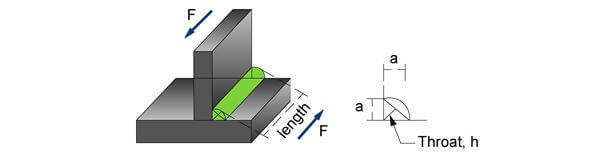
Figure 3: This figure shows a fillet weld with forces acting in shear.
Fillet welds are the most common type of weld. Since it is the most common type of weld, you can most likely expect to have a fillet weld problem on the exam. Fillet welds are known to fail in shear, thus you should expect a problem that requires you to find the shear stress in a fillet weld. In order to calculate the shear stress in a fillet weld, due to an external force, you need to find the area that the force acts upon. In a fillet weld, the area is the length multiplied by the throat. The throat is shown as the variable “h” in the previous figure. However, you will often be given the height and width of the weld, which is shown as “a” in the previous figure. Through trigonometry, the relationship between “a” and “h” is shown for a 45 degree triangle.

Figure 4: The relationship between a fillet weld’s throat and side of a fillet weld can be found through trigonometry.
If the sides of the weld are equal, where “a” is equal to the height of the weld in the y-direction and “a” is equal to the width of the weld in the x-direction, then the angle theta is equal to 45 degrees. Thus the relationship between “a” and “h” can be shown below.

The technical study guide also covers the following Welding and Brazing topics:
- Welding Properties
- Brazing Properties
- Welding References
- Fillet Weld under Torsion
- Fillet Weld under Bending
- Welding Symbols
Bolts, Screws and Rivets
Bolts, screws and rivets are types of fasteners. These types of fasteners are not as strong as the joints created with welding, but are stronger than adhesives. Fasteners are defined as a device that connects two or more components. There are a lot of different types of fasteners but the PE exam luckily focuses only on bolts, screws and rivets.
In preparation for the PE exam, you should be able to calculate the forces and stresses that act upon bolts, screws and rivets. This section will guide you through these calculations. But you should have the correct references to be able to complete these calculations. These references include tables on Bolts, Screws and Rivets that cover the following properties for each type of fastener:
Bolt, Screw and Rivet Properties: Class, grade, tensile area, length, major diameter, minor diameter, tensile strength, yield strength, proof strength, hardness and thread dimensions.
Finally, this section will cover forces in a group of fasteners (bolts, screws and rivets).
A bolt is a type of fastener that passes through a hole in two or more components and is then tightened by a nut on its threaded end. A screw has similar construction, with a head and a threaded end. The difference between a screw and a bolt is in their intended use. Bolts are used to fasten together two unthreaded components with a nut. Screws are used to join components, where at least one of the components is threaded. For example, a screw that is drilled into two pieces of wood joins two threaded components. The screw creates the threads within the wood. A bolt that connects two pieces of wood would require a non-threaded hole. The bolt would be set into the hole, connecting the two pieces of wood. A nut would then be used to tighten the two pieces together.

Figure 5: : A bolt connects two non-threaded components. A bolt is placed at the threaded end of the bolt to secure and tighten the two components together.
The nut is threaded and matched to the bolt. The lifting and lowering torque required to tighten or loosen the nut is similar to the equation shown for power screws. If you encounter a question with a threaded bolt or screw, you may either have to check this section or the power screw section.
The last aspect of bolts is that bolts are removable, similar to screws. Rivets on the other hand are permanent fasteners.
Tension or Clamping Force
The main PE questions will revolve around the purpose of the bolt, which is to clamp two components together. The clamping force causes the bolt to stretch, which means the bolt is undergoing tension. The bolt can also undergo more tension as the joined components undergo more loading. The bolt must be strong enough to resist this tension. The bolt will experience other external loads like moment and shear loads, which will be discussed later.
When a bolt is secured to two components, it produces an initial tension also known as pretension or bolt preload. This is the first force that acts upon the bolt.
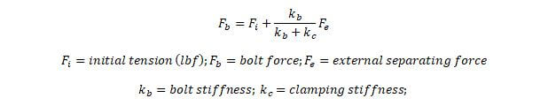
The next force is the force due to an external tension load. When a tension load acts upon the two components that are joined together, the amount of external load applied will be divided between the two components and the bolt(s). The equation that determines how much of the load acts upon the bolt and how much of the load acts upon the two components is shown below. In this equation, the initial tension load is added to a fraction of the external tension load or separating force. This fraction is determined by the ratio of the bolt stiffness to the sum of the bolt and clamping stiffness.
The bolt stiffness and clamping stiffness values are very difficult to calculate. It is highly unlikely that you will have to calculate these values and it is more likely that you will be given the external force that acts upon the bolt. However, just for completeness, the bolt stiffness equation is shown below. The clamping stiffness will vary greatly on the material of the two components selected. The calculation is also much more involved due to the geometry of the bolt in relation to the two joined components.
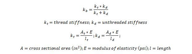
The stiffness of the bolt is a function of the stiffness of the threaded and unthreaded parts of the bolt. The stiffness for each of those parts can be found by multiplying the area of that part by the modulus of elasticity divided by the length of that part.
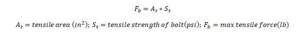
On the PE exam, you may be asked to calculate the maximum tensile force that a bolt can withstand. This can be found by multiplying the tensile area by the tensile strength of the bolt.
In order to complete these types of problems quickly, you must have your Machinery’s Handbook readily available and you must have the bolt tables tabbed. These tables provide the tensile area of bolts and tensile strength for various bolts of different materials. Another term that may be provided in your references is the proof load. This is the maximum tensile force that can be applied to a bolt that will not result in plastic deformation. The yield strength is the amount of tensile force that will produce a specific amount of permanent deformation.
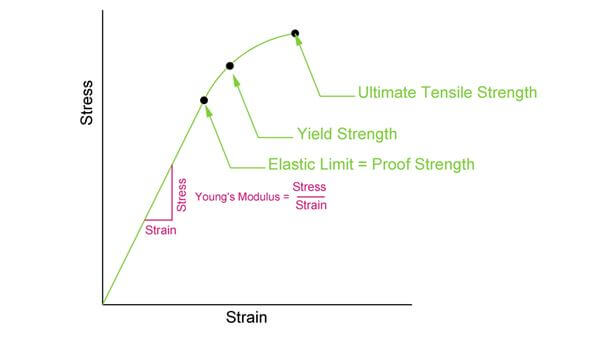
Figure 6: The tables in the Machinery’s Handbook provide values for proof strength, yield strength and ultimate tensile strength for various bolts. Make sure you choose the right value to match the PE problem.
If the tensile stress area is not provided in the tables and the PE exam asks you to calculate the tensile stress area, then you can use the following equation for threaded areas. For non-threaded areas it is simply pi multiplied by the radius squared.

The technical study guide contains the following topics on bolts, screws and rivets:
- Thread Shear
- Fatigue
- Screws
- Rivets
- Concentric Tensile Force on Fastener Group
- Concentric Shear Force on Fastener Group
- Concentric Tensile & Shear Force on Fastener Group
- Eccentric In-Plane Force on Fastener Group
- Eccentric Out-Of-Plane Force on Fastener Group
Adhesives
Adhesive bonding is another method of joining two or more components. Adhesives are advantageous when weight is an issue and a lesser fastening strength is required. Welding and brazing most often have the largest fastening strength, then bolts, screws and rivets and finally followed by adhesives. On the PE exam, you should be familiar with adhesive property tables which contain shear strength and peel strength values.
Shear flow was previously discussed as the shear stress over a distance. In adhesives, shear flow is used to determine the shear stress in the adhesive. The typical example is several beams glued together to make a single, stronger beam. Since the components are separate pieces, there will be transverse or longitudinal forces that will cause the glue to shear.
Shear flow in adhesives uses the same equation as shear flow in fasteners, which is reiterated below.
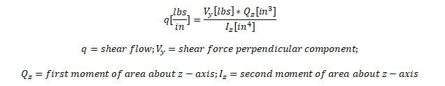
Once you have calculated the shear flow, then you can determine the shear stress in the adhesive. For example, if the shear flow is 100 lbs/in and the total length of the component is 10 in, then the total shear stress in the adhesive is 10 psi.
The technical study guide contains the following additional topics on adhesives:
- Adhesive Materials
- Adhesive Data Sheets
- Adhesive Stresses
- Single Lap Joint
- Double Lap Joint