![]()
Engineering Pro Guides is your guide to passing the Mechanical & Electrical PE and FE Exams
Engineering Pro Guides provides mechanical and electrical PE and FE exam technical study guides, practice exams and much more. Contact Justin for more information.
Email: contact@engproguides.com
FE EXAM TOOLS
Electricity & Magnetism for the
Mechanical FE Exam
1.0 Introduction
Electricity and Magnetism accounts for approximately 3 to 5 questions on the Mechanical FE exam. The mechanical discipline intersects with the electrical when mechanical energy is converted to electrical and vice versa. Hence, the mechanical engineer should have a basic understanding of electricity and magnetism. The most common application is the production of power via a generator and the reception of power through equipment via motors. Other applications include control circuits, variable frequency drives, and the effects of mechanical equipment on power quality. Remember that only the basics of the “Electricity and Computer Engineering” section of the NCEES FE Reference Handbook will be tested during the exam. The questions must also relate to the topics below.
2.0 Charge, Current, Voltage, Power & Energy
2.1 CHARGE
An electric charge, Q, describes the number of electrons or protons there are. It can be positive (protons) or negative (electrons) and is measured in Coulombs (C). For example, one electron has -1.6x10⁻¹⁹ C of charge and one proton has +1.6x10⁻¹⁹ C. The movement of electrons is the foundation of how electricity works. It is unlikely that charge itself will be tested. It is more important to understand how charge is used to describe other concepts like current, power, voltage, and energy.
2.2 CURRENT
Current, I, is the movement of charge and is more specifically defined as the rate at which charge flows. It is represented in terms of Amps, where one amp is equal to the movement of one Columb of charge per second.


For steady flow, current can be calculated as:

One characteristic to distinguish is that current flows in the opposite direction of electrons. Current flows from positive to negative, see the green arrow in the figure below, start at the positive end of the battery, loop around the circuit and end at the negative end. Electrons on the other hand are attracted to positive charge, so it will flow from negative to positive, as shown in red below.

Figure 1: Current flows in a circuit from the positive end of the battery to the negative, as shown in green, while electrons flow from negative to positive.
Direct current (DC) is the supply of current in one direction. As mentioned previously, current flows from the positive voltage terminal to the negative terminal in a circuit. Current is deemed positive when it flows in this direction. Current is considered negative when it flows from a negative terminal to a positive terminal. DC current is a constant source and does not switch between negative and positive. The simplest example of a DC source is a battery.
Alternating current (AC) is able to supply current in both directions, positive to negative and negative to positive. This is shown in the graph below, where the current can be positive (above the 0-axis) or negative (below the 0-axis). Alternating current is what is supplied by the electric company to buildings. Alternating current is further discussed in the Alternating Circuits topic.
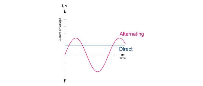
Figure 2: In an AC circuit, current can alternate its flow from positive to negative. In a DC circuit, current is constant.
2.3 VOLTAGE
Voltage, V is the potential energy in electricity; it is the amount of energy held in one charge and is given in units of volts.

Voltage is measured between two points because potential energy is the difference in energy. This potential energy in a circuit is what drives the flow of electrons, and therefore the current, from one point to the next. A battery is typically a source voltage, supplying energy into a circuit. A voltage can also be measured across a load or a resistor, this is known as voltage drop since the energy is being absorbed by the load.
2.4 RESISTORS
To complete a circuit, wires are connected from a voltage source to a load, which is represented by the resistance. Resistance is measured in units of ohms (Ω). It is the opposition to the flow of current. One ohm is described as the level of resistance that will allow 1 ampere to flow when 1 volt is applied to a circuit. The following figure depicts a basic circuit with current flowing from a voltage source, then through a resistor.

Figure 3: A basic DC circuit, current flows from positive to negative.
Ohm’s law describes the relationship between voltage, resistance and current. The voltage in a circuit is equal to the product of the current and the resistance in the circuit.

As voltage increases, in a constant resistance circuit, current will rise. As current increases, in a constant resistance circuit, voltage will rise.
2.5 POWER
The next concept that you must understand is electrical power. Power is the rate at which energy flows and is given in units of Watts (Joules per second). The power equation in basic circuits is given below and states that real power is equal to the product of the voltage and the current. Real power is given in terms of watts.

If you combine Ohm’s law and the real power equation, then you will find two equations that show power as a function of resistance. These equations, along with Ohm’s Law can be found in the NCEES FE Reference Handbook.

The term power factor will commonly be introduced when connecting to the main power grid. Power factor is essentially the quality of the power that enters a building. Power factor is discussed in detail under the AC Circuits topic.
2.6 ENERGY
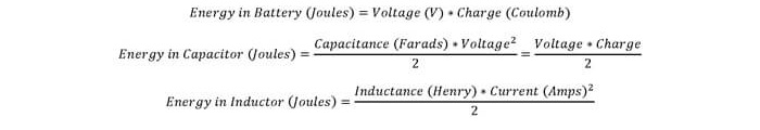
Electric energy can be represented in two forms, kinetic and potential. Energy is potential when it is stored in a battery, capacitor, or inductor. As the energy is distributed to a circuit, it is converted to kinetic energy. Finally, when it flows through a load, the energy is consumed in forms such as heat, light, or mechanical energy. The following equations represent energy across various elements. They may be found in the NCEES FE Reference Handbook. The first is the most important to know. In mechanical engineering, electrical energy is normally represented as Wh, kWh, or MWh.

Example: A 20 hp motor operates for 8 hours a day on a daily basis. How much energy (kWh) is consumed in 5 years. Assume the motor is operating at full load and is 100% efficient.
Solution: Since efficiency is not a factor, the motor will consume 20hp of electric power. Then, the energy consumption is calculated as:

After 5 years, the motor will consume 217,744 kWh of electricity.
The following three will likely not be used, but is shown for its relationship between capacitance, inductance, and charge to energy. The AC Circuits section discusses capacitors and inductors in further detail.
3.0 Current & Voltage Laws
3.1 OHM’S LAW
Ohm’s law is explained in the resistors section above.

3.2 KIRCHHOFF’S LAWS
There are two Kirchhoff laws that are necessary for the FE exam, (1) Voltage Law and (2) Current Law. The voltage law or KVL (Kirchhoff’s Voltage Law) states that the sum of voltages around a circuit loop is equal to zero. The current law or KCL (Kirchhoff’s Current Law) states that the sum of the current into and out of a node is equal to zero.
3.2.1 Kirchhoff’s Voltage Law (KVL)
KVL describes the principle that in a circuit loop all voltage produced must be used by the devices in the circuit. There cannot be a change in voltage in a circuit loop.
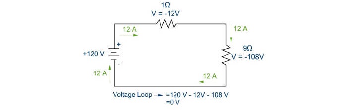
Figure 4: The sum of the voltages around a loop must equal zero.
KVL is also applicable when there is more than one voltage source in a circuit. Notice that the positive and negative terminals of the voltage sources are oriented in the same way, such that both voltage sources contribute positive voltage to the circuit.
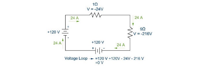
Figure 5: The sum of the voltage around a loop with multiple voltage sources will equal zero.
If the terminals of the two voltage sources were situated opposite from one another, then one voltage source would contribute positive voltage and the other would contribute negative voltage. The voltage source that contributed negative voltage would be similar to charging a battery and the positive voltage contribution would be a discharging battery
.KVL also applies to circuits with multiple loops. Each loop must have its voltage sum equal to zero.
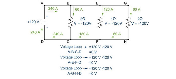
Figure 6: KVL is applicable in any loop.
3.2.2 Kirchhoff’s Current Law (KCL)
KCL describes the principle that the current entering any node in a circuit must equal the current leaving the node. If you look at the previous circuit, specifically node “B”, you will notice that there is 240 A entering the node and 240 A leaving the node, with 60 A leaving on path B-C and 180 A leaving on path B-E. The next equations show more examples of KCL for various nodes in the previous figure.

4.0 Equivalent Circuits
A complex circuit is made up of multiple devices and wires arranged in either series or parallel. These arrangements define the flow of current and the change in voltage with the following principles.
4.1 SERIES CIRCUITS
In a series circuit, the resistances are added to determine the equivalent resistance.

Capacitors in series are found by taking the inverse of the total sum of one over each capacitor.

Inductors in series are added to determine the equivalent inductance.

Further explanations of capacitors and inductors are described in the AC circuit topic.
4.1.1 Example: Solving for Resistors in Series
Once you have a single equivalent resistance value, then you can determine the current flow through the circuit. The main concepts to understand are as follows:
(1) Current is constant through a series circuit and (2) resistances are summed to determine equivalent resistance.
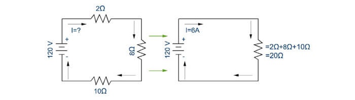
Figure 7: The equivalent resistance for resistors in series is found by adding the resistances.
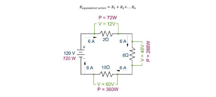
Figure 8: Voltage drop and power use in a series circuit
• Voltage Drop
In the previous figure, the voltage drop is found through each resistor by taking the current flow and multiplying it by the resistance. As you can see, the voltage drops add up to 120V in accordance with KVL and the voltage drop magnitude varies directly with the resistance level in accordance with Ohm’s law.
• Power Consumption
In the previous figure, the power consumption is found through each resistor by taking the current flow and multiplying it by the voltage drop.
4.2 PARALLEL CIRCUITS
In a parallel circuit, the voltage drop across each path is the same and the circuit splits between the different paths.
In a parallel circuit, resistors are found by taking the inverse of the total sum of one over each resistor.

Capacitors in parallel are found by taking sum of all capacitors.

Inductors in parallel are found by taking the inverse of the total sum of one over each inductor.

Further explanations of capacitors and inductors are described in the AC circuit topic.
4.2.1 Example: Solving for Resistors in Parallel
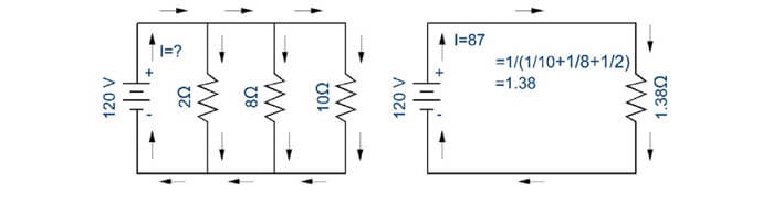
Figure 9: Equivalent resistance of resistances arranged in parallel.
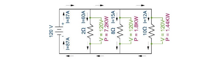
Figure 10: Parallel circuits
• Voltage Drop
In the previous figure, the voltage drop is found through each resistor by using KVL and realizing that in every loop the total voltage drop must equal to zero. Thus the voltage drop through resistors, (2 Ω), (8 Ω) and (10 Ω) are all equal to 120 V. The voltage drop through each resistor and the resistance value will also help to determine the amount of current through each resistor.
• Power Consumption
In the previous figure, the power consumption at each resistor is found by taking the current flow through each resistor and multiplying it by the voltage drop.
4.3 EXAMPLE: SOLVING FOR EQUIVALENT CAPACITOR
In the example below, find the equivalent capacitors:
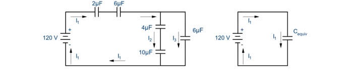
Figure 11: Example for Finding Equivalent Capacitance

4.4 EXAMPLE: SOLVING FOR EQUIVALENT INDUCTORS
In the example below, find the equivalent inductor:
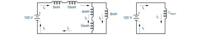
Figure 12: Example of Finding Equivalent Inductance

5.0 AC Circuits
Alternating current is most commonly used on the FE exam and in most power applications. Alternating current describes the alternating directions of flow in a circuit. Current quickly alternates flow direction from positive to negative many times a second. In the figure below, positive current is shown flowing in a clockwise direction in the figure on the right and this flow direction corresponds to the positive portions of the graph on the left.
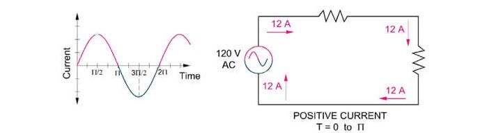
Figure 13: Alternating current consists of positive and negative flowing current. This figure shows positive current flow.
In this second figure, negative current is shown flowing in a counter-clockwise direction. The current flow in the figure on the right corresponds to the negative portions of the graph on the left.
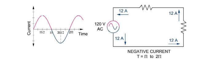
Figure 14: Alternating current consists of positive and negative flowing current. This figure shows negative current flow.
5.1 FREQUENCY
The frequency of an alternating current wave is the number of cycles completed in one second and is given in terms of hertz. For example, in the USA, the standard frequency for alternating current is 60 hertz (HZ). This means that 60 cycles are completed in one second. In Europe, the standard is 50 hertz (HZ). In the previous figures, 1 second would correspond to the 2π value, where the one cycle is completed.

Another term that is closely related to frequency is angular frequency. Angular frequency is the rotational frequency of alternating current and is given in terms of radians per second. For example, if one rotation is completed in one second, then the angular frequency is 2π. Angular frequency is related to physical frequency through the following equation.

5.2 RMS AND MAX
In an AC circuit, the voltage and current are constantly varying in magnitude over time. The RMS method is used to find the average or effective value of a constantly varying value. You may want to simply calculate the average of the value over time to get the effective value of the current or voltage, but in a simple AC circuit, the average will be zero because there are both positive and negative values. The term root mean square is found by taking the sum of “n” number of points along the waveform, squaring each value, summing all “n” values and then taking the square root of the sum.
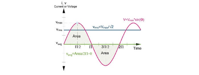
Figure 15: This figure shows the relationship between average, root mean square and maximum values in a sine wave.
The fundamental equation for calculating RMS is shown below. The variable “V” is used for voltage but this variable can also be exchanged for “I” for a current waveform.

In a basic sinusoidal waveform, the RMS value can be mathematically determined for an infinite number of “n” points. This value is shown as 0.707 times the peak value of the sinusoidal graph.

5.3 COMPLEX NUMBERS
Complex numbers are the best way to represent AC circuits. Complex numbers consist of a real component and an imaginary component. These numbers are used to represent phasors in the electrical engineering field. For example, in terms of power, the real component represents real power and the imaginary component represents reactive power. The phasors are also used to represent resistance, inductance and capacitance.
First, you need to understand the two forms of representing complex numbers, (1) Rectangular form and (2) Polar form. Then you must learn the rules necessary to add/subtract and multiply/divide complex numbers quickly for the FE exam.
...
SEE TECHNICAL STUDY GUIDE FOR MORE
The technical study guide continues to cover resistance, inductance, capacitance and impedance. Also included is discussion on apparent power, real power, reactive power and power factor.
6.0 Motors & Generators
On the FE exam, there is a topic titled motors and generators within the Electricity & Magnetism section. The equations in the NCEES FE Reference Handbook on this topic of motors are geared towards finding the motor size that is needed to power mechanical equipment like a fan or pump. The topic of generators is used to generate power, through the use of a turbine. The turbine is discussed in Section 12.0 Thermodynamics, but it is briefly introduced in this section too. The primary focus of this topic is on motors and finding the motor size that is necessary to power a fan or pump.
A generator uses the mechanical energy from rotation to produce alternating current electrical energy. Typically a turbine is used to provide the mechanical energy. Motors use alternating current electrical energy to produce mechanical energy in the form of rotation.
When selecting mechanical equipment, the mechanical engineer must coordinate the power requirements with the electrical engineer. This is done through the following four steps: (1) Determine Mechanical Horsepower, (2) Determine Fan/Pump Brake horsepower, (3) Determine Motor Horsepower and finally (4) Determine Electrical Power.
Additional discussion on calculating fan and pump power is provided in the Fluid Mechanics section. The main objective of the following explanations is understanding how to derive the electrical power delivered to the motor. The following equations are provided in English units with embedded conversion factors. For equations in SI units, see the Fluid Mechanics section.
6.1 MECHANICAL HORSEPOWER (HP)
Mechanical power (HP in English units and watts in SI units) is defined as the amount of power required to meet the needs of the system in question. For example, if the mechanical equipment was a pump, then the mechanical HP would be the amount of power generated by a certain flow rate (gallons per minute, GPM) at a certain pressure (ft of head). For a fan, the mechanical work would be the amount of power generated by a certain amount of flow rate (cubic feet per minute, CFM) at a certain pressure (inches of water gauge, in wg.). These equations can be found below.
SEE TECHNICAL STUDY GUIDE FOR MORE
The technical study guide continues to cover mechanical horsepower, fan or pump brake horsepower, motor horsepower and electrical power.
7.0 Practice Problems
7.1 PRACTICE PROBLEM 1 - MOTORS
Background: A 460 V, 1 phase, 60 HZ, 20 BHP pump. The motor has an efficiency of 75%. There is a power factor of 0.85.
Problem: What is the current in amperes supplied to the motor?
(a) 29
(b) -38
(c) 44
(d) 51
7.2 PRACTICE PROBLEM 2 - MOTORS
Background: A 10 BHP fan operates for 4000 hours in the year. The motor is 85% efficient and the power factor is 0.85. Energy cost is $0.25 per kilowatt-hour.
Problem: How much does it cost to operate the fan in one year?
(a) $7,460
(b) $8,770
(c) $10,320
(d) $12,140