![]()
Engineering Pro Guides is your guide to passing the Mechanical & Electrical PE and FE Exams
Engineering Pro Guides provides mechanical and electrical PE and FE exam technical study guides, practice exams and much more. Contact Justin for more information.
Email: contact@engproguides.com
FE EXAM TOOLS
Statics for the
Mechanical FE Exam
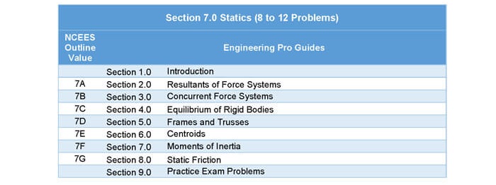
1.0 Introduction
Statics accounts for approximately 8 to 12 questions on the Mechanical FE exam. These questions can cover statics, but not dynamics. The statics topic on the NCEES exam is similar to a common statics college engineering class. Statics is the study of components at equilibrium, which means the components are at rest or at zero acceleration. This topic includes vectors, free body diagrams, moments, reaction forces, first moment of area, static friction and second moment of area. These concepts and skills are used to solve problems on pulleys, cables, springs, beams, trusses, frames, etc.
The NCEES FE Reference Handbook Statics section has some basic equations for the topics below, but it does not explain the skills and concepts necessary to use these equations. You should learn the skills and concepts presented in this section and go through the handbook to confirm that you know how to use the basic equations. You may also need to know some of the Mathematics equations like law of cosines and other trigonometry equations presented in the Mathematics section. The handbook also presents screw threads but this is covered more in Section 15.0 Mechanical Design and Analysis in this book.
2.0 Resultants of Force Systems
As previously stated, statics is the study of mechanical components at equilibrium, which means the components have zero acceleration or are at rest. The material presented on statics focuses on the key equations and skills necessary to complete the possible problems within this topic on the FE exam.
2.1 VECTORS
Vectors are used to visualize forces and moments in this section and in Section 9 Mechanics of Materials and they are used to visualize movement in Section 8.0 Dynamics, Kinematics and Vibration. This section will focus on vectors being used to describe the magnitude and direction of force or moment. On the FE exam you must be able to translate words or diagrams into force/moment vectors and you must be able to add/subtract vectors and multiply/divide vectors by scalars.
Vectors can either be represented in a rectangular form or a polar form. The rectangular form consists of an x-component and a y-component. These values are used to represent the magnitude in the x and y directions. In real applications, there will also be a z-component, but for the purposes of the exam you most likely will only need the x and y components. The polar form is shown as a magnitude and an angle. The magnitude describes the length of the vector while the angle determines the direction.
Vector forms are discussed in the Mathematics section of this book, but is repeated here for completeness.
2.1.1 Rectangular Form
The rectangular form is shown as, x plus the y component. The y component is shown as j and the x component is shown as i.

The rectangular form is used when adding and subtracting vectors and follows the same rules as normal addition and subtraction, where only like terms can be added and subtracted. For example, “Example A” plus “Example B”, is solved with the following process.

The rectangular form can also be understood via a graphical format, where the x-axis represents the real component and the y-axis represents the imaginary component.
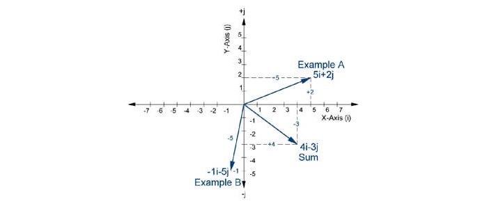
Figure 1: Example “A” vector, example “B” vector and the sum of the two vectors is shown in the above graph.
2.1.2 Polar Form
The polar form is best understood in its graphical format. The format consists of a phasor magnitude at a phasor angle relative to the x-axis.
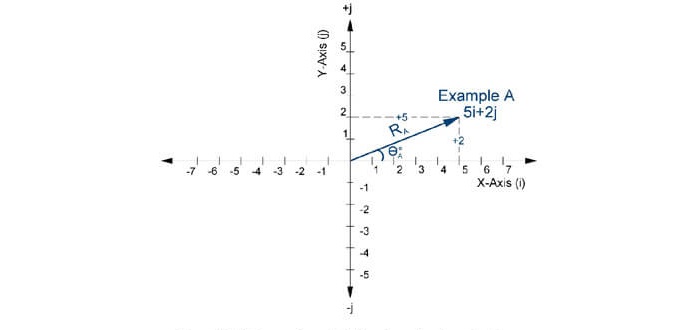
Figure 2: A phasor shown in both polar and rectangular form.

In the above example, the polar form is converted from the rectangular form by using the Pythagorean Theorem to find the radius (i.e. the magnitude) and the inverse tangent to find the angle. The polar form is not typically used for adding or subtracting, but it is used for multiplication and division. When multiplying or dividing two polar forms, you must multiple/divide the radiuses and add or subtract the angles. If the polar forms are being multiplied, then you must add the angles and if you are dividing one polar form from another then you subtract the divisor from the dividend.

2.1.3 Converting Polar and Rectangular Forms - Calculator
During the exam, you will need to convert from polar form to rectangular form and vice versa. You will need to convert between the two forms in order to carry out multiplication/division or addition/subtraction. You should be able to quickly convert between the forms with your calculator. This will help to save you time for more difficult tasks during the exam.
Discussion on using your calculator to convert polar and rectangular forms is included in the Mathematics section of this book.
2.1.4 Vector Mathematical Operations
Discussion of adding, subtracting, multiplying, and dividing vectors are provided in the Mathematics section of this book.
2.2 FORCE
Force is the action that pushes or pulls an object. The force can be invisible like gravity, electrical or magnetic. In mechanical design, the only invisible force that is tested is gravity. Visible forces due to pulleys, gears, hydraulics and much more are tested on the Mechanical FE exam.
One of the first set of concepts you learn in Statics are Newton’s Three Laws of Motion. The application of these laws is tested on the exam and it is assumed that you learned these laws and other fundamental Statics concepts in college/university.
First Law: The first law states that an object at rest or at constant velocity (zero acceleration) will remain that way, until an unbalanced force acts upon the object.
Second Law: The second law states that an object subject to an unbalanced force will be subject to an acceleration that is directly proportional to the unbalanced force and inversely proportional to the object’s mass.

Third Law: The third law states that objects that are in contact with each other will experience a force opposite the subject force acting upon the object. This force is called the reaction force. This law is useful in the beam type problems.
The units of force may be given in US customary system (USCS) or the International System (SI) units for the FE exam. This means that force is measured in pounds (lbf) for USCS. Mass is given in terms of slugs ((lbf*s^2)/ft) or in pound-mass (lbm). See the Fluid Mechanics section for discussions on pound-force and pound-mass. For SI units, force is measured in Newtons ((kg*m)/s^2 ) and mass is given in terms of kilograms (kg). Make sure you know where to find the conversions between the two sets of units in your NCEES FE Reference Handbook.
3.0 Concurrent Force Systems
A concurrent force systems is a collection of force vectors acting upon a single point. A concurrent force system is assumed in the next topics, Equilibrium of Rigid Bodies and Frames & Trusses.
4.0 Equilibrium of Rigid Bodies
Equilibrium of rigid bodies describes the problems that are at rest and all its moments and forces are balanced such that the sum of the moments and forces acting upon a rigid body is zero. A rigid body is defined as a mass that does not deform when a force acts upon it. This makes all the following equations simpler because you do not need to account for forces that are internalized within a mass.

In order to determine if the forces and moments balance out, you will need to be able to draw a free body diagram to visualize the forces and moments acting upon a rigid body.
4.1 FREE BODY DIAGRAM
On the exam, there will be questions with diagrams and sometimes without diagrams. But one thing that will not be provided at any time on the exam will be the forces and directions of these forces. You will need to be able to draw a free body diagram of the forces acting upon an object in order to create the equilibrium equations that you will need to solve the problems. The first step is to assign a frame of reference and assign which direction is positive and negative. Typically, forces acting in the left direction (x-axis) and down direction (y-axis) and out of the page (z-axis) are assigned a negative force. Forces acting in the right direction (x-axis), up direction (y-axis) and into the page (z-axis) are assigned a positive force.4.2 EQUILIBRIUM
If an object is not moving, then the object is in equilibrium. This means that the forces acting upon an object in the x, y and z directions will sum to equal zero. On the exam, you can use these equilibrium equations to solve for the unknowns.
4.3 SPRINGS
A good example of equilibrium equations are the equations developed for spring applications. When an external force acts upon a screen, there is an equal and opposite reaction produced by the spring. The spring force is a function of the stiffness constant of the spring and the displacement produced within the spring.
Figure 3: If the spring is not moving, then the external force will be equal to the spring force. The spring force will be equal to the spring’s stiffness value multiplied by the displacement.

4.4 PULLEYS AND CABLES
Another example of developing equilibrium equations can be shown for pulleys and cables. A pulley is a wheel on an axis that is securely attached to a surface. The pulley is used to change the direction of the cable’s force. A cable is used to transmit force (tension) from one end to another end of the cable. The important thing to remember is that the tension in a cable is the same at any location along the cable.
Figure 4: The tension in a cable is constant. Ta equals Tb.
At first glance, the downward forces do not balance out and it would appear that the cable and pulley are not in equilibrium. However, the pulley is securely attached to the upper surface. This produces reactionary forces that balance out the downward forces as shown in the free body diagrams below.

Figure 5: In this figure the downward forces acting on the pulley are due to Ta and Tb. Tb is purely in the y-direction, but Ta can be split up into its x and y directions.
The reactionary force that acts upon the pulley must be equal and opposite to these downward forces. This reactionary force is called “R” in the diagram below.

Figure 6: The reactionary force value acting in the upward y-direction is equal to the sum of Tb, Ta,y. The reactionary force value acting in the right x-direction is equal to Ta,x.
The spring and pulley/cable examples should give you an idea of the type of questions that will be asked on the FE exam with respect to static equilibrium when only forces are involved. The next section will introduce moment equilibrium equations.
4.5 REACTIONS
The following reaction diagrams visualizations can help you construct your free body diagrams. When you see these types of supports on the exam you should be able to determine what types of reaction forces will occur at the support. The first set of diagrams are in the isometric view to show that there can be x, y and z reaction forces, but for the purposes of the exam you will most likely only need to know the second set of reaction diagrams in two dimensions.

Figure 7: This is a simple or roller support that only provides reaction forces in the upward direction.

Figure 8: This is a pinned support that provides reaction forces in all directions.

Figure 9: This is another view of the roller support that only provides reaction forces in one direction.

Figure 10: This is a pinned support that provides reaction forces in all directions. There is no reaction moment.

Figure 11: The fixed support has reaction forces and moments in all directions.

Figure 12: Two dimensional view of the reaction forces for the most common types of supports.
5.0 Frames & Trusses
Frames and trusses are constructed of members, typically steel members in mechanical engineering. Trusses are joined by pins and are two force members, while frames are typically welded and are multi-force members. This difference will be discussed in more detail in the individual paragraphs on frames and trusses.
5.1 TRUSSES
In a trust the joints are pinned together. If you remember from the previous reactions topic, pinned joints cannot transfer moments. This means that the members are free to rotate. This also results in each member of a truss to be subject to either a tensile force that wants to pull apart the member of a compressive force that wants to push a member together.
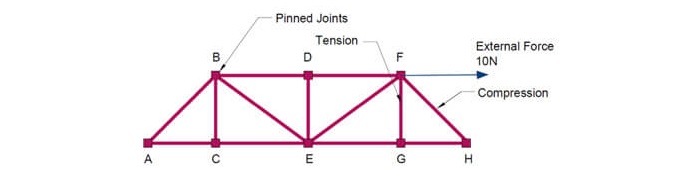
Figure 13: A truss consists of members that are connected via pinned joints. A truss is typically constructed of triangular shapes. In this figure an external force is applied that pulls the truss to the right. If everything is pinned such that the joints do not move. There will be a compressive force in member F-H and a tensile force in F-G. You can visualize compressive and tensile forces in the other members too, but they are not shown in this figure.
There are two methods that are used to calculate the forces within the members of a truss, (1) Method of Joints and (2) Method of Sections. You should be familiar with both methods and when to use each method.
5.2.1 Method of Joints
The method of joints is one method used to calculate the forces within the members of a truss. In this method, you look at the forces acting on a joint and since the joint is not moving, then the net force acting upon the joint must be equal to zero. Most problems will be coplanar, meaning that most problems will only involve the X and Y coordinates. In this method you must balance the forces acting in the x and y-directions. It is important to be able to draw an accurate free body diagram.
The following figure will be used as an example to show you how to use the Method of Joints.

Figure 14: This example will be used to show the method of joints. Assume a right angle at joint G. FG forms a right angle with member GH. Please note that support H does not provide any reactive force in the X-direction.

Figure 15: This figure shows a free body diagram of the previous figure. It focuses on the forces acting upon only joint F. At joint F, there is an external force of 10 N acting in the right x-direction. This external force must be balanced by the forces within members FH and FH.
Once you have the free body diagram, then you need to balance the forces in the x and y-directions.

Figure 16: In this figure the forces acting in the x-direction are shown. The x-component of force FFH must be equal and opposite as compared to the external force value.
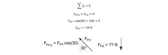
Figure 17: In this figure the forces acting in the y-direction are shown. The y-component of force FFH must be equal and opposite as compared to the vertical force in member FG.

Joint H can then be analyzed using the same method.

Figure 18: This figure shows that the horizontal force within member GH will oppose the x-component and the reactive force at joint H will oppose the vertical, y-component from member FH.

Joint G is finally analyzed using the same method.

Figure 19: In this figure, the reactive forces at support G counteract the forces in members FG and GH.

5.2.2 Method of Sections
This section is discussed in the technical study guide.
5.2 FRAMES
This section is discussed in the technical study guide.
6.0 Centroids
Centroids are the center of an area and are typically used to find the center of mass of an object with uniform density. The centroid of an area may sometimes be outside of an area, like in the most common example of a ring. The centroid is found by dividing the first moment of area by the area. So first, you will learn how to calculate the first moment of area.
6.1 FIRST MOMENT OF AREA
The first moment of area should not be confused with the moment of inertia which will be discussed in the following section. The first moment of area is equal to the sum of the area multiplied by the distance to an axis. The axis is the centroid of the area. There are two first moments of area, one about the x-axis and the other about the y-axis for a 2-dimensional object.

In the equations above, “y” is the distance from the centroid in the y-direction and “x” is the distance from the centroid in the x-direction. If the axis is changed from the centroid, to another axis, then you must use the parallel axis theorem to convert the first moment of area to another axis. The parallel axis theorem will be discussed in the Moments of Inertia topic.
6.2 CENTROID CALCULATION
This section is discussed in the technical study guide.
7.0 Moments
Moment describes the force on a body that causes the body to rotate about an axis. Moment can also be called Torque. The most difficult part in completing problems with Moment or Torque is drawing the free body diagram. You must be able to imagine forces being applied to a body’s axis at different distances from the axis in such a way to rotate the body about its axis.
7.1 FREE BODY DIAGRAM
This section is discussed in the technical study guide.
7.2 EQUILIBRIUM
This section is discussed in the technical study guide.
7.3 CALCULATING MOMENTS OF INERTIA
This section is discussed in the technical study guide.
7.3.1 Second Moment of Inertia (Area Moment of Inertia)
This section is discussed in the technical study guide.
7.4 PARALLEL AXIS THEOREM
This section is discussed in the technical study guide.
7.5 RADIUS OF GYRATION
This section is discussed in the technical study guide.
8.0 Static Friction
Friction is the force that resists the movement of surfaces that slide upon one another. Most problems on the FE exam will assume that the surfaces are frictionless. If a friction factor or frictional force is not provided, then it is safe to assume that the surfaces are frictionless. However, there should be a few problems that will incorporate friction into the problem. For these few problems it is important to understand two main concepts.
First, the object in question will have a normal force that is perpendicular to the contacted surface. Secondly, there will be a force that is tangent to the surface that is opposite to the movement of the object. If the object is not moving, then the force is opposite the direction that the object is approaching movement. For example, if the object is on a slope, then the impeding motion is downward and the frictional force will be opposite this motion.
There are two types of friction, static friction and kinetic friction. When an object is at rest, there will be no motion until the force to cause movement is greater than the maximum force due to static friction. Once the movement force is greater than this value, then the object will move. Once the object is moving, the friction force that opposes movement will now be equal to the equation for kinetic friction, shown below.

There are three types of problems involving static friction that can be on the FE exam. These problems are for a block on an angled surface and pulleys.
8.1 ANGLED SLIDING BLOCK WITHOUT EXTERNAL FORCE
In this scenario a block is placed on an angled surface. The block is subject to both gravitational force and frictional force. However, only a portion of the gravitational force is applied in the x direction, since the other portion is applied in the y-direction. Also in this angled scenario, the x-axis and y-axis are rotated. The x-axis is in the direction of the angled surface and the y-axis is perpendicular to this surface.
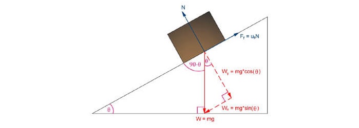
Figure 30: A block sliding down an incline is subject to frictional forces in the opposite direction of movement.
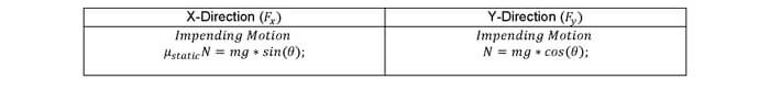
Similar to the first example, the forces are summed for both the x and y directions.
8.2 ANGLED SLIDING BLOCK WITH EXTERNAL FORCE
This section is discussed in the technical study guide.
8.3 BELTS AND PULLEYS FRICTION
This section is discussed in the technical study guide.
9.0 Practice Problems
9.1 PRACTICE PROBLEM 1 – BALANCING MOMENT
A beam of weight 100 lbs is supported by a tension cable. The dimensions are shown in the diagram below. What is the tension in the cable?

(A) 100 LBS
(B) 130 LBS
(C) 160 LBS
(D) 190 LBS
9.2 PRACTICE PROBLEM 2 – BALANCING MOMENT
A beam has a weight of 450 lbs and there is a point load of 150 lbs as shown in the figure below. What is the reaction force at point A?

(A) 100 LBS
(B) 150 LBS
(C) 250 LBS
(D) 350 LBS