- HOME
- FE EXAM
- PE EXAM
- DESIGN TOOLS
- COURSES
- STORE
- ABOUT
- CONSULTING
![]()
Engineering Pro Guides is your guide to passing the Mechanical & Electrical PE and FE Exams
Engineering Pro Guides provides mechanical and electrical PE and FE exam technical study guides, practice exams and much more. Contact Justin for more information.
Email: contact@engproguides.com
FE EXAM TOOLS
Mechanics of Materials for the
Mechanical FE Exam
by Justin Kauwale, P.E.
Introduction
Mechanics of Materials accounts for approximately 8 to 12 questions on the Mechanical FE exam. Mechanics of Materials questions basically will cover calculating the stress or strain due to different loadings, like axial loads, bending loads, torsional loads and shear loads. In addition, you will have to calculate the displacement, shear force and moments for beams and the buckling forces and stresses in columns.
The equations shown in the NCEES FE Reference Handbook on Mechanics of Materials is comprehensive and all of these equations are fairly simple and easy to use. This means that the equations do not have any complex math. After going through this section, you should be familiar with the different types of loadings and all the equations within the handbook and should be able to quickly recognize when to use each equation for each problem.
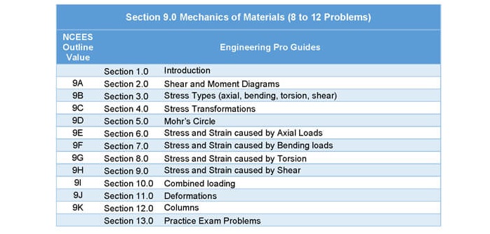
2.0 Shear and Moment Diagrams
Shear and moment diagrams are used to graphically show how forces, displacement and moments change depending on the location within a component. The components that you will most likely need to know are beams, since the shear and moment diagrams included in the NCEES FE Reference Handbook are only for beams.
However, before you use the diagrams you should understand the concepts behind the beam diagrams and the resulting equations. Once you have a good grasp on the concepts and how to use the equations, then you should be able to solve these types of problems.
There are three main types of beam diagrams, (1) Free Body Diagram, (2) Shear Diagram and (3) Moment Diagram. The first step (1) is to determine the forces acting upon the beam in order to construct the beam diagram. Beams can be loaded with a load at a point or a distributed load along the entire length of the beam. The loads are primarily downward and in order to create equilibrium there will be reaction forces upward at the supports. Equilibrium equations for both forces and moments about each of the supports are used to find the reaction forces. The forces must equal zero, since the beam is restricted from movement. Also the sum of the moments at each of the supports must be zero, since the beam is restricted from twisting. Once you have found all loads and reaction forces, then you can construct the free body diagram.
The next step (2) is to construct the shear diagram. The shear diagram describes the internal forces within the beam at any point of the beam. This diagram is created by splitting up each segment separated by a point force or reaction force. Then you must cover all external forces to the right of each point and sum up all external forces and this sum is the shear force at that point.
The final step (3) is to construct the moment diagram. The moment diagram is comprised of the moment at any location along the length of the beam. The moment diagram is constructed in a similar fashion as the shear diagram.
In practice, shear diagrams and moment diagrams are not often re-constructed, since the diagrams have already been documented. Please see the NCEES FE Reference Handbook for completed beam diagrams with equations. Beam diagrams will most likely be used on the FE exam in order to find the maximum stress in the beam or the maximum deflection in the beam. This can be done by using the given beam diagrams and using the corresponding equations. However, there may be conceptual type problems which will require you to have an understanding of how these diagrams are constructed. The next few pages will show a few diagrams and walk you through some points on the diagram.
In practice, beam supports can be classified based on how much the beam is restricted by the support.
• Loose support (simply supported): A loose support, which would be the same as the simply support diagram, is used to support the weight vertically. The beam can be moved in all other directions. Including along the length of the beam (longitudinal) and perpendicular to the direction of the pipe (transverse). The beam is only restricted from moving vertically (up and down).
• Loose support with longitudinal guide: This type of support includes the loose support but also has a restriction on the transverse. The beam will not be allowed to move perpendicular to the direction of the beam. This would include putting a clamp around a beam to stop the side to side movement.
• Loose support with transverse guide: This type of support includes the loose support but also has a restriction on the longitudinal. This would stop the beam from expanding and contracting in the longitudinal direction.
• Loose support with anchor: This type of support restricts movement in both the longitudinal and transverse direction.
2.2 SIMPLE BEAM WITH A UNIFORMLY DISTRIBUTED LOAD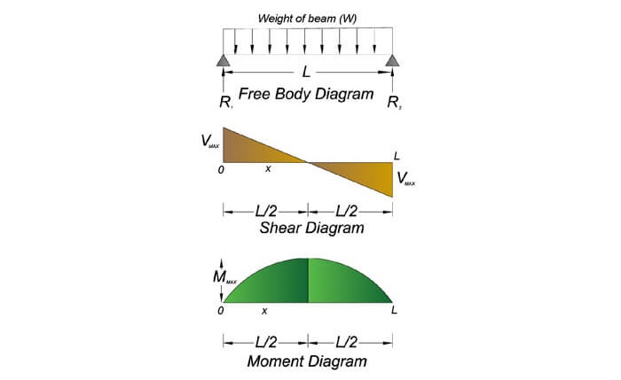
Figure 1: Simple beam with uniformed load diagrams
This diagram is typically used when a beam is supported at both ends for only the weight of the beam. The downward force is equal to the weight of the beam. The weight is evenly distributed evenly the entire length of the beam, which is why the vectors are of equal size.

There will be upward reaction forces at the support that will counteract the weight of the beam. The force at each support will be equal to one-half the entire weight.

The next figure shows the shear force diagram. The shear force acting at any point “x” on the beam is governed by the below equation. The shear force is at its maximum at the supports. You can see that when 0 and L are inserted into the equation for x, the value will be of magnitude equal to ½ the weight.

The bending moment acting at any point “x” on the beam is governed by the following equation. The moment is at its maximum at the center. The moment will be equal to zero when “x” is equal to “L” or “0”.

The deflection at any point “x” on the beam is governed by the following equation. The deflection is at its maximum at the center.

The moment can then be used to find the maximum stress in the beam. The maximum stress in the beam will help to influence the beam dimensions and material choices. The maximum stress will be discussed in the bending topic.
2.3 SIMPLE BEAM WITH A CONCENTRATED LOAD
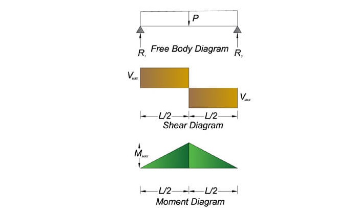
Figure 2: Simple beam with concentrated load diagrams.
This diagram is typically used when a beam is supported at both ends and it is used to support a concentrated load. The downward force is equal to load. There will be upward reaction forces at the support that will counteract the concentrated load. The force at each support will be equal to one-half the entire weight.

The next figure shows the shear force diagram. The shear force acting at any point “x” on the beam is either +P/2 or –P/2. The shear force is at its maximum at the supports. The slope of the line in this diagram is straight, because unlike the distributed load, the only forces acting upon the beam are the reaction forces and the concentrated load. The previous diagram had external forces acting on the beam throughout the entire length, which changed the shear force at each point along the beam.
The bending moment acting at any point “x” on the beam is governed by the following equation. The moment is at its maximum at the center. The moment will be equal to zero when “x” is equal to “L” or “0”.

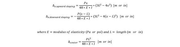
The deflection at any point “x” on the beam is governed by the following equation. The deflection is at its maximum at the center.
The moment can then be used to find the maximum stress in the beam. The maximum stress in the beam will help to influence the beam dimensions and material choices. The maximum stress will be discussed in the bending topic.
2.4 FIXED END BEAM WITH A UNIFORMLY DISTRIBUTED LOAD
This section is discussed in the technical study guide.
2.5 FIXED END BEAM WITH A CONCENTRATED LOAD
This section is discussed in the technical study guide.
3.0 Stress Types (Axial, Bending, Torsion, Shear)
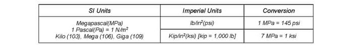
Stress is described as the internal force acting upon a specific cross sectional area within an object. The equation below shows that stress is equal to the force divided by the area. The units of stress are in “psi” or “kips” for imperial units and Megapascal for SI units.

You may encounter both sets of units on the FE exam, so you should be familiar with both and should commit these conversions to memory.

The strength of a material with respect to stress is the maximum stress that a material can withstand before failing. For brittle materials, failure occurs at ultimate stress.

For ductile materials, the maximum stress for a design could be the yield stress, because an object will no longer perform to design if it passes the yield strength and becomes permanently deformed.
On the FE exam, you should be careful to make sure you use the correct maximum stress for the correct type of material and situation. The following two graphs illustrate the difference between the yield stress and ultimate stress for brittle and ductile materials.
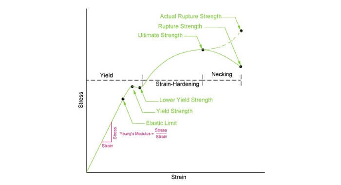
Figure 5: This figure shows the stress and strain relationship for ductile materials. The yield strength is typically used as the maximum design stress for ductile materials.
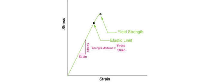
Figure 6: This figure shows the stress-strain relationship for brittle materials. The yield strength is equal to the ultimate strength and is typically used for maximum design stress.
There are four types of stress discussed in this section, (1) Axial, (2) Bending, (3) Torsion and (4) Shear.
3.1 AXIAL
Axial stress is due to any stress caused by a force acting along the axis of an object. Axial stress is also known as tension or compression stresses. The force divided by the incident cross sectional area is equal to the axial stress and the stress can either be tensile or compressive. The definitions of tensile and compressive are shown in the figures below.
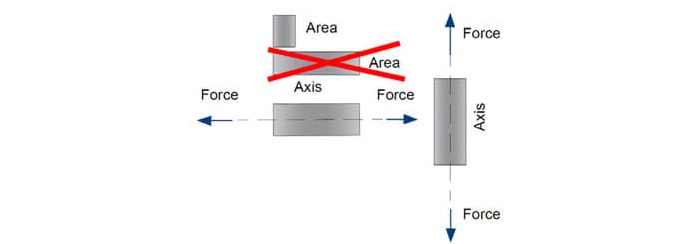
Figure 7: Forces that pull apart an object cause a tensile stress. The axial force acts along the axis, so the area used in the calculations must be the cross sectional area is perpendicular to the force vector.
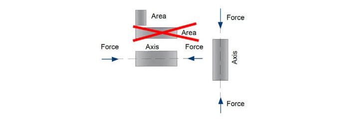
Figure 8: Forces that push together an object cause a compressive stress. The axial force acts along the axis, so the area used in the calculations must be the cross sectional area that is perpendicular to the force vector.
The equation for axial stress is shown below. Remember that the area used for this equation is the area that is perpendicular to the force vector.

This section is discussed in more detail in the technical study guide.
3.2 SHEAR
Shear stresses are the opposite of axial stresses. These stresses are caused by forces acting in parallel to a cross sectional area. The equation for shear stress is the same as axial stress, except the area is the area parallel to the force vector.
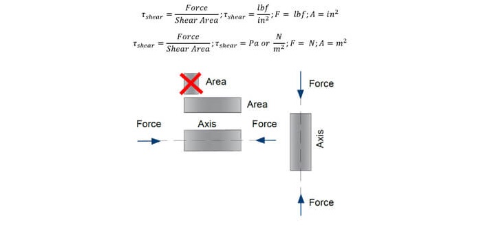
Figure 9: The shear stress is found by divided the force by the area that is in parallel to the force vector.
This section is discussed in more detail in the technical study guide.
3.3 BENDING
Bending stresses are discussed more in the beam topic. Bending stress can also be called a flexure stress. Bending stresses put the top half of an object in compression and the bottom half in tension. So the stress varies depending on the location in the object. In the previous topics on shear and axial stresses, the stress is consistent throughout the entire object’s cross section. The equation for bending stress is shown below. Bending stress is a function of the moment, distance from the neutral axis and the moment of inertia.


Figure 10: The force above causes a bending stress that varies as you move away from the neutral axis.
This section is discussed in more detail in the technical study guide.
3.4 TORSION
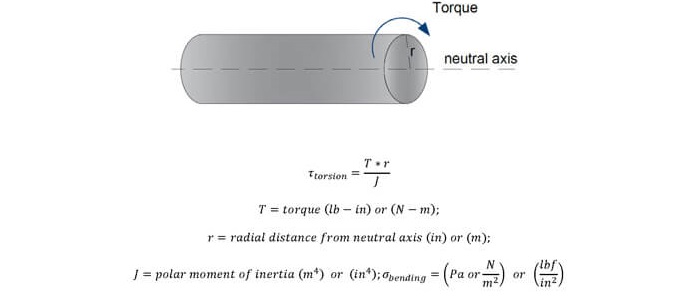
Torsional stresses occur when a twisting moment is applied. Similar to how the bending force causes a bending moment, a torsional force can causes a torsional (twisting) moment. This twisting moment is simply called torque. The equation for torsional stress is shown below. Torsional stress is a function of the torque, distance from the neutral axis and the polar moment of inertia.
This section is discussed in more detail in the technical study guide.
4.0 Stress Transformations
Stress transformation equations are used to transform the stresses that occur in one set of axes (x, y & z) to another set of axes (x’, y’ and z’). This technique is used when you need to find the stress acting upon a cross sectional area that isn’t on the original set of axes.
This section is discussed in more detail in the technical study guide.
4.1 TRANSFORMATION EQUATIONS
This section is discussed in more detail in the technical study guide.
4.2 PRINCIPAL STRESSES
This section is discussed in more detail in the technical study guide.
5.0 Mohr's Circle
5.1 MOHR THEORY - DUCTILE
Mohr’s theory is another theory used to assess when a material will fail. This theory is used when a material does not have similar compressive and tensile yield strengths. Mohr’s theory can be best understood through the use of Mohr’s Circle. This circle is a representation of 2-d stresses in the tensile/compressive direction and in shear. The circle is used to analyze complex stresses to determine the principle stresses that are applied to a component. The principle stresses can then be compared to the tensile, compressive and shear strengths.
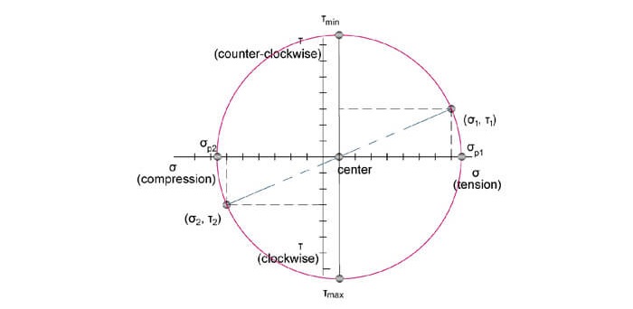
Figure 11: Mohr’s circle is used to find the primary stresses in tension, compression and shear.
The complex stresses of (σ_1,τ_1) and (σ_2,τ_2) are typically given in a FE problem. Then you must use Mohr’s circle to find the principal forces that act in tension, compression and shear. These principal forces are shown as the extreme points on the circle.

Figure 12: The given stresses that act upon an element within a component are shown in this figure. Notice how the clockwise and counter-clockwise shears correspond to the points shown on the previous figure. Also notice how the tension and compression stresses are shown in this figure correspond to the correct location in the previous figure.
Mohr’s circle is created by first determining the center point of the circle from the complex stresses given in the problem. The center is found through this equation.

Next you must find the radius of the circle. The radius is found through the use of the Pythagorean Theorem. First you take the difference in the x-directions, to find the x-length of the triangle. Then do the same for the y-direction. Finally, square root the sum of the squares to find the hypotenuse of the triangle, which is equal to the diameter of the circle. The radius is equal to ½ the diameter.

Finally, the principal stresses can be found by adding or subtracting the radius to the center values.

This section is discussed in more detail in the technical study guide.
5.2 MOHR THEORY - BRITTLE
This section is discussed in more detail in the technical study guide.
6.0 Stress and Strain Caused by Axial Loads
Axial loads will cause tension and compression. On the FE exam you may encounter problems where an object is under a force due to tension or compression. A tension force is a force that attempts to pull a material apart along its axis. A compression force is a force that squeezes a material together along its axis. The forces due to tension and compression will cause a stress within the material that is equal to the force divided by the cross sectional area that is perpendicular to the force.
6.1 STRAIN
This section is discussed in more detail in the technical study guide.
6.2 AXIAL THERMAL STRESS AND STRAIN
This section is discussed in more detail in the technical study guide.
7.0 Stress and Strain Caused by Bending Loads
Bending occurs when slender objects are used to support loads perpendicular to their length. The most common type of problem that you will encounter on the FE exam is the bending of beams. Bending of beams was first introduced earlier in this section under shear and moment diagrams. This section will tie together the material properties and the beam diagrams to determine the strength of a beam during bending.
Once you use the force and moment diagrams from the previous section to determine the maximum forces and moments in the beam, then you can determine the stress in the beam through the following equation. The maximum stress in the beam is equal to the maximum moment divided by the section modulus of the beam. The section modulus will be defined later in this section. The equation to find the stress in a beam is shown below.

7.1 SECTION MODULUS
This section is discussed in more detail in the technical study guide.
7.2 DEFLECTION
This section is discussed in more detail in the technical study guide.
8.0 Stress and Strain Caused by Torsion
Torsional loading is the act of twisting an object, typically a rod or shaft in the Machine Design field. When the shaft is twisted, a torque is applied that causes the shaft to deform as shown in the figure below. The solid line is the new twisted axis and the dotted line shows the original axis. The angular difference between these two lines is called the angle of twist.
This section is discussed in more detail in the technical study guide.
8.1 SOLID CIRCULAR SHAFTS
This section is discussed in more detail in the technical study guide.
8.2 TUBULAR CIRCULAR SHAFTS
This section is discussed in more detail in the technical study guide.
8.3 SHAFTS OF VARYING DIAMETER
This section is discussed in more detail in the technical study guide.
8.4 PARALLEL AXIS THEOREM
This section is discussed in more detail in the technical study guide.
8.5 TORSION FAILURE
This section is discussed in more detail in the technical study guide.
9.0 Stress and Strain Casued by Shear
Shear stress is the stress that is in parallel to the area, as opposed to stress in tension or compression which acts perpendicular to the area. The figure below shows a force that acts in parallel to the area. The shear stress is defined as the shear force divided by the area.
This section is discussed in more detail in the technical study guide.
9.1 SHEAR STRESS
This section is discussed in more detail in the technical study guide.
9.2 SHEAR STRAIN
This section is discussed in more detail in the technical study guide.
9.3 POISSON’S RATIO
This section is discussed in more detail in the technical study guide.
10.0 Combined Loading
A combined loading problem occurs when you have multiple stresses acting upon an object. You could have a bending and axial load or a torsional and axial load or any other combination of loads. A combined loading problem will most likely not be on the exam, because the calculations will take much longer than 2-3 minutes. However, you should be familiar with the process, because they may ask you to complete part of a combined loading problem. In order to solve these types of problems, you must calculate the stress and strain due to each load. You also have to calculate the direction of the stress and strain due to each load at the point in question, then you can add-subtract the vectors for stress and strain due to each load. An example will be shown below to illustrate this process.
This section is discussed in more detail in the technical study guide.
11.0 Deformations
Deformation is the change in shape of an object. The change in shape is characterized by the strain values that were discussed in the previous topics. Deformations were shown in bending, torsion, compression, tension and combined loadings.
Two main types of deformation were also briefly introduced in Topic 3.0 Stress Types, (1) Elastic and (2) Plastic deformations.
Elastic deformations are also called permanent deformations. This means that the deformation has permanently changed the shape of the component. Plastic deformations can return back to their original shape. There is a certain point on the stress-strain graph called the elastic limit that indicates when a deformation will switch from plastic to elastic.
This section is discussed in more detail in the technical study guide.
11.1 AXIAL LOAD
This section is discussed in more detail in the technical study guide.
11.2 SHEAR LOAD
This section is discussed in more detail in the technical study guide.
12.0 Columns
This section is discussed in more detail in the technical study guide.
12.1 BUCKLING
This section is discussed in more detail in the technical study guide.
12.2 CRITICAL BUCKLING LOAD
This section is discussed in more detail in the technical study guide.
13.0 Practice Exam Problems
13.1 PRACTICE EXAM PROBLEM 1 – BEAM
A wood beam is situated as shown in the figure below. The material has strength of 900 psi. The beam shall be designed to have a safety factor of 1.0. What should be the dimension of the height of the beam? Assume the height of the beam is 2 times the width of the beam.

(a) 0.89 in
(b) 2.03 in
(c) 2.55 in
(d) 5.84 in
13.2 PRACTICE EXAM PROBLEM 2 – BEAM
A W 8 x 10 beam has an allowable stress of 50 ksi and dimensions as shown below. What is the maximum weight per foot that the beam can support?

(a) 120 lb/ft
(b) 210 lb/ft
(c) 289 lb/ft
(d) 420 lb/ft
13.3 PRACTICE EXAM PROBLEM 3 – BUCKLING
This section is discussed in more detail in the technical study guide.
13.4 PRACTICE EXAM PROBLEM 4 – TORSION
This section is discussed in more detail in the technical study guide.
13.5 PRACTICE EXAM PROBLEM 5 – SHEAR STRESS
This section is discussed in more detail in the technical study guide.
13.6 PRACTICE EXAM PROBLEM 6 – STRESS-STRAIN
This section is discussed in more detail in the technical study guide.
13.7 PRACTICE EXAM PROBLEM 7 – STRAIN ENERGY
This section is discussed in more detail in the technical study guide.
13.8 PRACTICE EXAM PROBLEM 8 – SHEAR AND MOMENT DIAGRAMS
This section is discussed in more detail in the technical study guide.
13.9 PRACTICE EXAM PROBLEM 9 – SHEAR AND MOMENT DIAGRAM
This section is discussed in more detail in the technical study guide.
13.10 PRACTICE EXAM PROBLEM 10 – STRESS TRANSFORMATIONS
This section is discussed in more detail in the technical study guide.
13.11 PRACTICE EXAM PROBLEM 11 – STRESS FROM AXIAL LOAD
This section is discussed in more detail in the technical study guide.
13.12 PRACTICE EXAM PROBLEM 12 - STRESS FROM AXIAL LOAD
This section is discussed in more detail in the technical study guide.
13.13 PRACTICE EXAM PROBLEM 13 – AXIAL STRAIN
This section is discussed in more detail in the technical study guide.